


President
 |
|
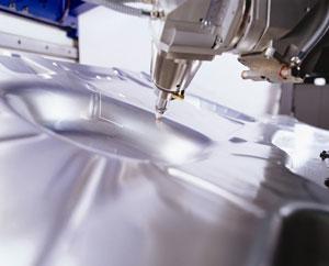
Photo courtesy of TRUMPF Inc. |
Part I of this series discussed the production of the CO2 laser beam and the interaction of the gases required to produce a quality beam. This part discusses beam delivery to the workpiece and the gases used to process the material.
CO2 laser beams used in materials processing must be maintained and delivered to the workpiece according to specific requirements. The basic ones are that the beam must:
A laser beam delivery system comprising a mirror telescope, beam-bending mirrors, and a phase shifter delivers the beam properly to the laser cutting head. Once the beam is delivered to the laser head, a focusing lens centers the point correctly to the work area.
The laser beam typically is enclosed in a protective pathway that must be filled with a gas to slightly above atmospheric pressure. Any particulate matter or particles that may absorb the laser light must be removed from this pathway. Compressed air is a common choice for this application, but air can contain moisture, particles, and oils that can decrease the laser beam's power and shorten the bean-bending mirror's life. Nitrogen is preferable because it is contaminant-free and does not affect the mirrors adversely.
Mirrors have finite lives that vary depending on the process and the required power level. The typical life is 200 to 600 hours. The beam power from the resonator outlet to the workpiece should be measured at regular intervals to determine mirror and beam degradation. Loss of mirror efficiency negatively affects the process. It also increases costs by delivering the beam at less than the required power level. A 10 percent decrease in mirror efficiency can increase electrical power consumption for the same operation by as much as 15 percent.
Laser Cutting Stainless Steel With Nitrogen |
||||||||||||||||||||||||||||||||||||||||||||||||||||||||||||||||||||||||||||||||||||||||||||||||||||||||||||||||||||||||||||||||||||||||||||||||||||||||||||||||||||||||||||||||||||||||||||||||||||||
|
||||||||||||||||||||||||||||||||||||||||||||||||||||||||||||||||||||||||||||||||||||||||||||||||||||||||||||||||||||||||||||||||||||||||||||||||||||||||||||||||||||||||||||||||||||||||||||||||||||||
| Figure 1 |
Once the beam has been properly delivered to the laser head, the beam's focus coupled with the assist gases at the proper pressure and flow completes the laser cutting process. Each material type requires the right combination of laser power, focusing lenses, and assist gas pressures and flows to do the job successfully. The laser manufacturer can supply this information in a format similar to the charts in Figure 1 and Figure 2. As shown in these charts, the parameters required to produce a quality laser-cut part vary with the material type and thickness.
Laser Cutting Carbon Steel With Oxygen |
||||||||||||||||||||||||||||||||||||||||||||||||||||||||||||||||||||||||||||||||||||||||||||||||||||||||||||||||||||||||||||||||||||||||||||||||||||||||||||||||||||||||||||||||||||||||||||||||||||||||||||||||||||||||||||||||||||||||||||||||||||||||||||
|
||||||||||||||||||||||||||||||||||||||||||||||||||||||||||||||||||||||||||||||||||||||||||||||||||||||||||||||||||||||||||||||||||||||||||||||||||||||||||||||||||||||||||||||||||||||||||||||||||||||||||||||||||||||||||||||||||||||||||||||||||||||||||||
| Figure 2 |
Undesirable factors to consider in laser cutting are:
Laser cutting should produce consistent cut surface quality and groove depth. Irregularities normally are caused by using incorrect assist gas pressure and flow or a cutting speed that is too fast.
The assist gases and supply equipment must be able to supply the gas to the laser head at the desired pressure and flow. Selecting the proper assist gas system is not always as simple as it might seem.
Among the items to consider when selecting the proper assist gases and supply system are:
Gas Required. Most lasers today can process various materials using different assist gases. Air, oxygen, and nitrogen are the most common. Argon and helium are required for titanium and some other materials. Each assist gas has pros and cons for each material. Consult your gas supplier for the most cost-effective system for your application.
Material Type and Thickness. Oxygen is the typical choice for carbon steel; air and nitrogen can be used to cut carbon steel, stainless steel, and aluminum.
Work Schedule. The more hours the laser is online, the greater the demand on the laser assist gas delivery system.
Laser Assist Gas Supply System Comparison |
||||||||||||||||||||||||||||||
|
||||||||||||||||||||||||||||||
| Figure 3 |
Once the assist gases have been selected, the supply method must be determined (see Figure 3). Gases must be supplied continuously, without interruption. High-pressure compressed-gas cylinders can be used, but these systems often have a high unit cost. Portable cryogenic cylinders, commonly referred to as "liquid" cylinders, have lower unit cost but limited pressure and flow capabilities. Cryogenic technology, commonly referred to as microbulk or minibulk, supplies both the required pressure and flow for laser cutting with oxygen, argon, and nitrogen assist gases.
Always remember that the CO2 process involves using gases for generating the laser beam, protecting beam delivery to the workpiece, and for cutting. Each step in the process is an independent application with unique gas requirements; the final finished part depends on the combination of all three. The higher the beam quality, the higher the part quality, and the more cost effectively the part is produced.


The Fabricator is North America's leading magazine for the metal forming and fabricating industry. The magazine delivers the news, technical articles, and case histories that enable fabricators to do their jobs more efficiently. The Fabricator has served the industry since 1970.
start your free subscription
Easily access valuable industry resources now with full access to the digital edition of The Fabricator.

Easily access valuable industry resources now with full access to the digital edition of The Welder.

Easily access valuable industry resources now with full access to the digital edition of The Tube and Pipe Journal.

Easily access valuable industry resources now with full access to the digital edition of The Fabricator en Español.
In this episode of The Fabricator Podcast, Caleb Chamberlain, co-founder and CEO of OSH Cut, discusses his company’s...


