


Contributing Writer
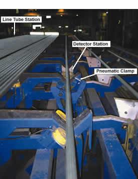 |
| An XRF system can be integrated at a detector station before final packaging. The tubes are held in place by a pneumatic clamp while the XRF detector is raised to make contact with the tube and perform the measurement. This process confirms the alloy grade of the material typically in two to three seconds. |
Recognizing the importance of minimizing such errors, some industry organizations have written guidelines for positive material identification (PMI) programs using a variety of analysis techniques.1 For PMI programs, X-ray fluorescence (XRF) is a suitable analysis technology. A nondestructive test (NDT), XRF requires little or no sample preparation.
Hand-held XRF devices commonly are used for spot inspection of material. Because they are small and portable, they are suitable for use at almost all locations in a manufacturing plant.
The limiting factors of such instruments are processing speed and the potential for human error. For critical, high-throughput measuring points such as prepackaging stations, XRF systems can be automated and installed inline to speed processing and minimize error. Automated XRF systems have the two main desirable characteristics of hand-held devices —compact size and durability. They are suitable for use in tight areas and can withstand mechanical vibrations from surrounding equipment and high temperatures of just-milled materials.
They differ from standard hand-held devices in that they have offline computing capability for interfacing with process control systems and increased data processing speeds to handle high production volumes.
 |
| Figure 1 An incoming X-ray ejects a K-shell electron from an atom of the material under test. An electron in the M shell loses energy as it transitions to the vacant K shell. It gives off energy in the form of fluorescence. |
An XRF instrument comprises an X-ray source, detector, and electronics. The analysis begins when the X-ray source, typically an X-ray tube or radioisotope source, irradiates the alloy. X-rays striking the atoms' inner shell (K-shell orbital) electrons impart energy, exciting the electrons and ejecting them from the atom, leaving a vacancy in the inner shell (see Figure 1). Electrons from higher-energy orbitals (L- and M-shell orbitals) release energy as fluorescence as they transition to fill the vacancy.
When the detector absorbs fluorescence, its conductance changes in proportion to the energy of the fluorescence, which then is processed by the electronics and displayed as a histogram. The histogram plots the intensity, or frequency of occurrence measured in counts per second, on the vertical axis and energy of the fluorescent signal, measured in kiloelectronvolts, across the horizontal axis (see Figure 2).
The fluorescent energy identifies the element, while the intensity of the fluorescence is a measure of the element's concentration.
 |
| Figure 2 An XRF histogram of stainless steel shows the presence of the main constituent (iron, or Fe) and several alloying elements, including chromium (Cr), manganese (Mn), cobalt (Co), nickel (Ni), copper (Cu), and titanium (Ti). |
The technique is applied to analysis of materials that have major constituents of atomic number greater than 11, sodium. In actual practice, the technique is used to determine composition of alloys with elements of atomic number 13 (aluminum) and higher.
Building a Spectrum Database. Known alloy standards are analyzed and each spectrum is stored in a database. The software compares the spectrum of an unknown production sample to those stored in the database. Acceptance is reported if the sample matches a stored reference (see Figure 3).
Pass or Fail? For PMI, the operator enters the product type into a process control system at the start of a production run, and the analyzer flags materials that do not conform to product specifications.
 |
| Figure 3 The XRF electronics package compares a histogram from an unknown production sample (left) to several histograms stored in its library (center) and determines that the production sample histogram matches a stored histogram for SS-304. |
If a flag is raised, the product is held in place to be reanalyzed. If a second flag is raised, the product is rejected from the process line. Alternatively, the line may be stopped for product diagnosis. If no flag is raised in the second test, the material is moved to the packaging station.
Integrating XRF equipment into a new manufacturing line is achieved through advance facility planning. Integration is based on two factors: instrument size and operating requirements. Incorporating equipment into existing lines is less convenient, but still is achievable. Some XRF instruments are available with a compact footprint to allow placement in tight areas, with few or no modifications to existing manufacturing equipment. The necessary modifications may include adding a test stand, a mounting bracket, an equipment enclosure for operator safety, or all three of these items.
Instruments are mounted to a bracket on existing line equipment or a test stand to provide a constant distance between the analyzer and the sample being tested. Instruments typically are positioned to contact stationary materials for the analysis, or they are located at small fixed distances (a few millimeters) for analysis of moving samples. Suitable integration points are locations where the product is stationary for two or three seconds, or where the product is moving with a portion of the surface exposed to the XRF instrument for a short period of time.
Instruments also may be used for inspecting finished products, with heat shielding available for PMI of hot samples.
Automated response mechanisms (for example, a motor-controlled ejection mechanism or an audible alarm) can be integrated with measurement results via an existing process control system such as a programmable logic controller interfaced with the instrument's central processing unit (CPU). In addition, measurement results and spectra can be transmitted via an RS-422 cable to a database for storage and retrieval. Records stored in this manner are available on demand to generate shift reports, monthly reports, or client-requested reports when necessary.
General operation of an automated XRF instrument is unattended; however, users should implement periodic procedures such as instrument warm-up, stability, and calibration verification routines after periods of inactivity. Calibration accuracy and stability are monitored by analyzing a reference standard and comparing the results to previous readings. Instruments compensate for small changes in detector response over time and variations in ambient temperature, humidity, or other environmental factors with prompts for routine maintenance and standardization procedures as necessary. These functions can be fully and automatically implemented.
Because the equipment emits X-rays, users must follow state licensing and registration requirements. These may include a licensing fee (initial or annual), simple registration of the device with the state at time of purchase, and periodic monitoring of equipment. Regulatory requirements for each state differ and may be found by contacting the Nuclear Regulatory Commission or the responsible state agency.
Julie Villescas is the technical marketing manager for Austin AI (Automation & Instrumentation), 2101 Donley Drive #108, Austin, TX 78758, 512-837-9400, fax 512-837-9434, jvillescas@austinai. com, www.austinai.com. Austin AI manufactures XRF instruments for process automation of solids, liquids, and powders.
HASTELLOY is a registered trademark of Haynes Intl, Inc.; INCONEL, INCOLOY, and MONEL alloys are all registered trademarks of Special Metals group of companies.
Note:
1. Pipe Fabrication Institute Standard ES-42; American Petroleum Institute Recommended Practice 578; and American Society for Testing and Materials Standard E1476-97.


The Fabricator is North America's leading magazine for the metal forming and fabricating industry. The magazine delivers the news, technical articles, and case histories that enable fabricators to do their jobs more efficiently. The Fabricator has served the industry since 1970.
start your free subscription
Easily access valuable industry resources now with full access to the digital edition of The Fabricator.

Easily access valuable industry resources now with full access to the digital edition of The Welder.

Easily access valuable industry resources now with full access to the digital edition of The Tube and Pipe Journal.

Easily access valuable industry resources now with full access to the digital edition of The Fabricator en Español.
In this episode of The Fabricator Podcast, Caleb Chamberlain, co-founder and CEO of OSH Cut, discusses his company’s...


