


Project Engineer
 |
Tube hydroforming technology continues to develop in ways that improve part utility, economy, and process robustness. Each advancement broadens the applicability of tube hydroforming by making designers aware of what is possible and of the economic and performance benefits to be gained. New parts with interesting features recently were put into production. The resulting cost of these features compared to their perceived value will play a large role in how development progresses.
Automobile hydroformed parts that have recently been produced include DaimlerChrysler Pacifica® roof rails and radiator enclosure, Jeep Grand Cherokee® (Europe) roof rails, and the Dodge Ram front-end structural module.
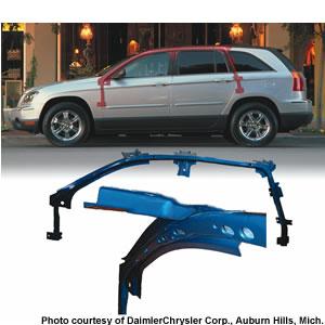
Roof Rails. The DaimlerChrysler roof rail part (see Figure 1) is a new high-volume production application. It extends from the A-pillar to the C-pillar. The center bracket attaches to the B-pillar. It was used by the manufacturer as a benchmark to evaluate the overall merits of hydroformed roof rails.
A roof rail part such as this provides strength and stiffness in a small package. Eight stampings are consolidated into two hydroformed assemblies, which eliminates the joints between them and the assembly operations that would have been required. In addition, a relatively small cell footprint is needed to assemble it.
 |
| Figure 2 |
The tube used is 2-inch (50.8-millimeter)-diameter by 0.059-in. (1.63-mm) mild steel. Seven brackets are gas metal arc welded (GMAW) to the assembly to attach the roof bows, air bag sensors, grab handles, and for assembly to the body side aperture of the vehicle. The large A-pillar bracket on the left is attached to the tube with three small welds, which are supplemented by a bead of adhesive sandwiched between the bracket and the tube. The three small welds hold the part in place until the adhesive cures in the paint bake oven at the vehicle assembly plant.
The cross section shapes vary along the part length, but their peripheries are equal to each other and to that of the tubular blank. Cross section corner sharpness as low as 4.2T is formed by closing the die with the tube full of very low internal water pressure, which generates compressive forces when the die periphery equals the tubular blank periphery. In addition to forcing the metal to fill the periphery, this pressure also discourages collapse. This contrasts with other processes where the corners are formed by expansion with internal pressure.
Compared to the previous design, the section strength along the length of the part is higher. This has allowed the vehicle designers to optimize other stampings in the body side aperture and reduce blank sizes.
All 35 holes in each tube are punched in the hydroforming die, which minimizes cost and provides dimensional stability. A number of clearance holes for fasteners and clips are mounted to the body side inner panel. Some of the other holes shown are for self-threading fasteners.
Material is extruded or folded into the holes to reduce weakening of the part cross section, which reduces the slug size. The self-threading fastener holes also are extruded to create a longer threaded portion for greater thread engagement, and the accompanying indentations act as lead-in for self-threading fasteners.
 |
The slugs are retained on all holes to prevent loose slugs from getting lodged in the part and resulting in rattling in the vehicle, as well as potential problems in the hydroforming die or damage to subsequent parts.
Making this line of medium-sized holes requires a number of punch units that must be positioned close to one another. Ensuring the punches did not interfere with each other and that the die strength was not compromised because of material removal required for the number of punch units posed a challenge.
The relatively low forming pressure helps in this respect. Dramatically increasing pressure to expand the cross section or calibrate the part proportionately increases the stress throughout the die. In addition, a higher internal pressure requires a larger punching assembly. Therefore, lower forming pressure allows much more in-die hole-punching flexibility, such as quantity, proximity, and hole size and style. This rationale is consistent with the stamping industry common practice, but is less pervasive with tube hydroforming.
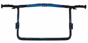
Radiator Enclosure. The latest of several tubular hydroformed radiator enclosures (see Figure 2) found in trucks and sport utility vehicles is used in a crossover vehicle. The upper and lower parts are made from 1.75-in. (0.445-mm)-dia. by 0.052-in.-(1.3-mm)-minimum-wall-thickness galvanneal mild steel tube. Several distinctive features are worthy of highlighting. The cross section corners are as sharp as 3T, less than the industry norm of 5T.
Nine brackets attach the part to the vehicle structure and hold other components. Six are welded by GMAW to the lower tube and three others are bolted in place.
 |
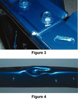
The radiator enclosure design called for a largely flattened cross section at each end of the top tube and a bolted joint between the upper and lower tubes (see Figure 3). This design is preferred so the fasteners draw the top and bottom together when they are tightened for good joint integrity, while the vertical stress that the part must handle is minimal. The small openings on either side are for fluid flow during forming.
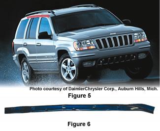
A sharply formed detail (see Figure 4) was needed to create clearance for a portion of the hood latch. As with the roof rail part, all holes are punched in the hydroforming die. The top tube has 27 holes (self-threading fastener holes, for auxiliary fastener holes, and oval-shaped holes for access to install auxiliary fasteners). The slugs for the end holes are removed.
European Roof Rails. The part used on the European version of the Jeep Grand Cherokee (see Figure 5) needed to meet different crash requirements in the European market. The part in Figure 6is relatively short but changes from a completely flattened end (see Figure 7) to a rectangular cross section on the other end, with 11 holes punched in the hydroforming die. The tube is 2-in.-dia. by 1.5-mm-min.-wall-thickness, 50,000-PSI-minimum-yield-strength, high-strength, low-alloy steel (HSLA).
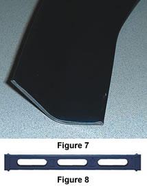 |
Lower Radiator Support. This lower radiator support (see Figure 8) part is a segment of a front-end structural module that is unusual for several reasons. One is that it has no bends. Another feature of this part are the six large holes that are cut in three pairs along the part length.
The holes allow better airflow into the engine compartment and they lighten the part. They are punched simultaneously using internal pressure to force the slugs outward. A technical challenge is to shear the peripheral length of these holes while maintaining pressure in the tube, because losing pressure stops the operation. The resulting development makes it possible to cut as many of these holes as are required for a part design. Other smaller holes are also punched in the hydroforming die for several purposes, including installation of self-threading and auxiliary fasteners.

The Tube and Pipe Journal became the first magazine dedicated to serving the metal tube and pipe industry in 1990. Today, it remains the only North American publication devoted to this industry, and it has become the most trusted source of information for tube and pipe professionals.
start your free subscription
Easily access valuable industry resources now with full access to the digital edition of The Fabricator.

Easily access valuable industry resources now with full access to the digital edition of The Welder.

Easily access valuable industry resources now with full access to the digital edition of The Tube and Pipe Journal.

Easily access valuable industry resources now with full access to the digital edition of The Fabricator en Español.
In this episode of The Fabricator Podcast, Caleb Chamberlain, co-founder and CEO of OSH Cut, discusses his company’s...


