


Product Manager of Tube Bending & Fabricating
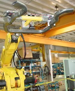
Figure 1: Robots often are used to move hydrofromed components from one station to another in an automated cell.
In the automotive industry, tubular hydroformed components have greatly improved product quality while opening up new design capabilities for future vehicles. The process helps produce engine cradles, A pillars, suspension components, roof rails—the list goes on. Produced to net shape, one hydroformed component often can replace multiple parts, resulting in assemblies with fewer parts, higher strength, and less cost.
When manufacturers start to look at hydroforming automation, they quickly discover that the auxiliary equipment and automation surrounding the press are central to making the investment viable—and profitable—on their factory floor. Indeed, proper planning can be the most important factor that determines success or failure.
Pre-hydroforming automation—equipment that processes a part before it is placed in the hydroform press—typically includes part debundlers, weld seam detectors, tube benders, pre-forming modules, lubrication modules, inspection devices, and a material handling system that moves parts from one module to another (see Figure 1).
Hydroformed tubes typically come in bundles banded together, and as part of an automated system, something must debundle them. Strap-style hoppers or paddle-type conveyor hoppers can debundle large-diameter tubes. Tube bundles are placed in the hopper, and an operator cuts the bands that hold the bundle together. A strap hopper (see Figure 2) has a heavy nylon strap that moves the tubes into an escapement, where they are then ready to be positioned in the weld seam detector. Paddle-type hoppers use metal conveyor paddles to move the tubes into an escapement.
Hydroforming and bending can seriously damage weld seams if they aren’t positioned properly. The seam must be positioned where the least amount of stress is put on the tube as it’s bent on a bender or formed in the hydroform press. For weld seam detection, many automated setups have a camera vision system that locates the weld seam as the tube rotates. Another technique is electro-magnetic sensing, which detects differences in the magnetic field as the tube is rotated past the weld seam area.
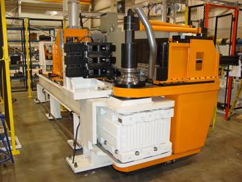
Before hydroforming, tubes often are pre-bent with a CNC bender to a shape that matches the hydroform die (see Figure 3). The machine’s multi-axis programmability allows it to bend multiple part configurations and make simple bend changes when required. Pre-form modules, consisting of a pre-form die placed in a press, come after or replace the CNC bender. These modules create a form on the tube to allow it to fit in the hydroform die cavity and aid material flow during the hydroform process.
Usually hydroforming requires lubrication on the tube’s outside surface before the tube reaches the hydroform die. This lube generally is applied in areas where the most work in the die is to take place.
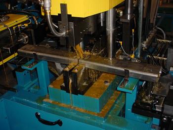
Post-hydroform equipment performs operations on a tube that cannot be completed in the hydroform die. For instance, hydroformed tubes often have seal plugs on them during hydroforming that must be removed later. In addition, some duplex parts are formed in one piece and then must be split in a later operation to make two production pieces. Shearing equipment can remove seal plugs and cut connected, duplex piece parts after hydroforming (see Figure 4).
Hydroformed parts often require contour cutting on the ends to ensure proper fit-up with other components for welding or assembly. Mechanical trim dies can make sense for high-volume, low-mix work (see Figure 5). They can be designed to intentionally leave the burr on the part that is created by the trim tools on the outside or the inside of the tube, based on downstream process requirements. Laser end trimming offers greater flexibility but at a higher price, while mechanical trimming is less expensive and slightly less flexible, but can operate faster than the laser.
In some instances, there are requirements to put holes into hydroformed parts that cannot be put in during the hydroform process. This is where mechanical punching, drilling, or laser cutting comes into play. When mechanically producing holes, parts are positioned over support mandrels whenever possible to allow for clean hole punching. If a mandrel cannot be used, parts can be located and clamped in a fixture; a drill module then inserts the hole. Laser processing cells can be used to remove seal plugs, split parts in half, cut special end trims, and cut holes in hydroformed parts. The laser, in fact, can replace mechanical shearing, trimming, and hole piercing equipment. Compared to mechanical tools, the laser costs more and operates slower. But it can be retooled and reprogrammed very easily to run future parts—a significant benefit that often outweighs its shortcomings.
Flow drilling equipment can insert self-tapping holes in parts. The flow drill tool “spin-burns? through the wall of a part, extruding or upsetting the material to leave a surface larger than the material thickness of the tube itself.
End forming equipment expands or reduces the size of the tube ends as required for the downstream application. Ends typically are expanded or reduced one material thickness, allowing the end of the part to mate properly to another part with the original end size.
Hydroformed components usually are marked for full part traceability. The Julian date and a part number can identify components for this purpose. Pin stamping, engraving, or etch-style systems can be used for this operation.
Parts washers clean off hydroform fluids and debris left on or in the parts after hydroforming and downstream processing. Washers can be loaded with a robot or part transfer device, and parts can be washed and dried in the same unit if desired.
Inspection or poka-yoke stations—which can include vision systems or lower-cost hard pins—check for the presence or absence of holes or other features put into the part by the hydroform die or post-hydroform processing equipment. These stations prevent the processing of incomplete parts downstream and identify problems with tooling in the upstream equipment.
Robots in hydroform cells move parts between stations, and customized robot end effectors grip parts to ensure positive placement in each station (see Figure 1). The robots’ key advantage is that they can be reprogrammed for various part geometries.
Robots aren’t the only option, however. High-speed transfers also can move parts from one station to another. Typically mounted overhead, these transfers can be powered with hydraulic, pneumatic, or electro-servo technology. Tooling on the transfer is usually dedicated to a particular part configuration, and may require changeout when part changeover is required.
Most cells require some type of automatic scrap removal for sheared seal plugs and slugs from piercing stations, etc. Such scrap must be removed from the system and conveyed into a containment bin. As for finished parts, robots can be used to place final components onto specially designed pallets or racks.
Developing an automated cell of any sort requires detailed planning, and hydroforming is no exception. All elements, from tube debundling to scrap removal, are like pieces of a puzzle—and if any one of them is missing or doesn’t fit, the entire system becomes ineffective.
Attention to detail ensures that no piece of the automation puzzle is left behind.
Planning for Hydroforming Automation, Step by Step

The Fabricator is North America's leading magazine for the metal forming and fabricating industry. The magazine delivers the news, technical articles, and case histories that enable fabricators to do their jobs more efficiently. The Fabricator has served the industry since 1970.
start your free subscription
Easily access valuable industry resources now with full access to the digital edition of The Fabricator.

Easily access valuable industry resources now with full access to the digital edition of The Welder.

Easily access valuable industry resources now with full access to the digital edition of The Tube and Pipe Journal.

Easily access valuable industry resources now with full access to the digital edition of The Fabricator en Español.
In this episode of The Fabricator Podcast, Caleb Chamberlain, co-founder and CEO of OSH Cut, discusses his company’s...


