


Project Engineer
 |
Closed-section structures have long been important in vehicle design.
Typically, these have been assembled with several stampings, because no practical way existed to form tubes into complex shapes at required quality levels. Holes were more costly than in stampings, and some types were impossible to produce because surface deformation was too severe.
Tube hydroforming removes these constraints and broadens the list of possible uses for tubing. Manufacturers can increase vehicle bending and torsional rigidity requirements by using hydroforming to reshape part cross sections, to attain the best stiffness, to eliminate joints, and to avoid interference with surrounding components.
It is important to ask the right questions to ensure the hydroforming method being considered offers the best design flexibility and economy.
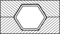 |
| Figure 1: This figure illustrates a simple cross-section shape. |
Traditional high-pressure hydroforming (HPH) forms relatively complex part shapes by expanding the whole tube. Pressure-sequence hydroforming also can be used to form complex parts. It can form most ductile metals, including high-strength, low-alloy, and stainless steels with sharper corners, thick-walled tube, and other difficult features.
Simple Hydroforming
Hydroforming in its simplest form uses a die cavity that is essentially the same periphery as the starting tube diameter. Cross-section shapes must be simple, as shown in Figure 1, and transitions between them gradually. Proper bend positioning and changing the cross-sectional shape around these shapes are particular problems. Internal pressure does not exceed the material yield strength after the die is closed.
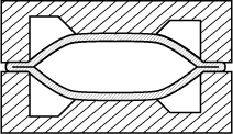 |
| Figure 2: Material in this illustration is being pinched inside a die cavity. |
Overly complex cross sections result in pinching (see Figure 2), during which material is crushed wall-to-wall between the die halves at the split line. These problems restrict the process but also have motivated its evolution.
On more complex parts, pinching can be prevented by using a die cavity that is up to 10 percent larger than the starting tube diameter along the part length (see Figure 3, top left corner).
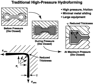 |
| Figure 3: The steps in traditional high-pressure hydroforming are shown here. |
Traditional hydroforming systems use high internal pressure after the die closes to stretch material into the die corners while forcing it against the die cavity surface as shown in Figure 3. Forcing material against the die cavity prevents sliding, which means stretching occurs over a decreasing portion of the tube periphery. As a result, average section expansion of 7 percent occurs, as shown in Figure 3, with a wall thickness reduction pattern exhibiting local thinning. Wall thinning is partly prevented for some distance from the part ends by feeding material into the die.
The focus of designing start tubes, final parts, and tools is producing parts with minimal internal pressure. This is economically beneficial because higher pressure increases press and delivery system size and cost, as well as cycle time, tool wear, and maintenance.
The whole tube is plastically deformed by stretching, which reduces springback. As corners are formed, tube wall thinning can exceed 20 percent as work hardening increases yield strength in direct proportion. As material thickness decreases, the pressure needed to stretch it decreases, as well.
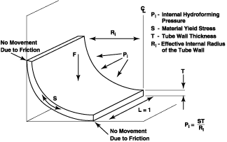 |
| Figure 4: As material yield stress (S) or the tube wall thickness (T) increase, so does the internal pressure (Pi) required to continue forming. Decreasing Ri increases the required Pi, which happens as the cross-sectional corners get sharper. |
The formula in Figure 4shows the relationship between pressure, material yield strength, wall thickness, and the cross-sectional corner inner radius for HPH parts.
Part Features. Internal fluid pressure must be high enough to stretch the material until the part completely forms. Both friction and the material's formability limit this potential. Additional operations such as annealing, part surface texturing, lubrication, cleaning and drying, or special materials with characteristics tailored to the process are often necessary to prevent failure. These measures increase part cost and should be minimized. Specifying the material to suit the process can compromise the ability of the part to satisfy its functional requirements.
At the start, the tube has a smaller periphery than the final desired part and is expanded to it. Material thinning in the corners may require thicker starting material to meet a minimum wall specification, cause weld quality variation, and reduce fatigue life from low remaining elongation.
Material. HPH makes high demands on material, which must have sufficient elongation to prevent bursting and be robust enough for production. These demands may eliminate many structurally and economically attractive material options.
High-elongation steel is being developed for hydroforming, but it will cost more than mild steel. High elongation improves formability and process robustness, but this steel also has low strength.
Low strength is advantageous for the process because it reduces internal pressure requirements. However, relatively small deflections can cause permanent deformation, which may not meet part needs.
Designing material properties for the manufacturing process often limits the ability to satisfy functional needs of the final part and opposes a trend toward high-strength materials, including high-strength, low-alloy (HSLA) steel.
Expanding the whole part by 10 percent will produce an average 10 percent gain in yield strength in mild steel. Yield strength may be even less since welding locally anneals the material where in-service stress is normally highest.
A material property called the n-value, or work-hardening exponent, is fundamental to successful HPH. It is a property closely associated with stretch forming, and as the value gets higher, local strain tends to be shared more evenly with surrounding material. Lower n-values may dictate increasing forming cycle time.
HPH applications may require stronger gas-tungsten-arc-welded (GTAW) or laser-welded-seam tubing, which has a production rate of 5 to 10 percent of the rate for electric-resistance-welded-seam (ERW) tube. A manufacturer may need to fully anneal tube stock, but more commonly, local induction annealing alleviates work hardening and increases elongation in the start tube bend areas. Black oxide forms unless an enclosed nitrogen atmosphere is used. The manufacturer should allow a cooling period of perhaps 20 minutes before hydroforming to avoid quenching. Galvanized tube is incompatible with HPH because of annealing. In addition, zinc can be abraded by the die cavity surface and accumulate on it.
Hole Punching and Cutting. Many automotive components require holes for attaching other parts, drainage, access, or fixturing. Holes on a hydroformed part can be made almost anywhere, either during or after forming. Punching them in the hydroforming die is the most economical method that also provides the most repeatable size and position. This method should be used whenever possible.
Wear inserts in the hydroforming die cavity and problems with in-die hole-punching — where end feeding occurs — can limit hole position and quantity. Large punch cylinders, which shear the material against the highest internal pressure, weaken the die. Maintaining die integrity with the high pressures needed also limits hole placement and number. This increases the need for costly and less accurate hole cutting after hydroforming.
Lubrication. High-pressure lubricants are used to improve metal movement over the cavity surface and reduce corner thinning. Surface texturing of the part or cavity may help retain lubricant at the interface.
Additional lubrication is necessary with annealing, since the process burns off all oils. Lubricant may need to be cleaned from the tube after hydroforming for welding or handling, and the tube should then be dried to prevent flash rust. However, the unprotected surface is then susceptible to rust from excess humidity or incidental water. The residue from cleaning must be dealt with, too. Waxy coatings that must dry between application and hydroforming may make these steps unnecessary, though.
Equipment Requirement. Each of the cited factors that increases required internal pressure proportionally increases the size of the needed hydraulic press, end feeding cylinders, and fluid delivery system.
Section Expansion During Hydroforming. With sufficient internal pressure to force material to the cavity surface, a manufacturer can use hydroforming to expand a part more than 10 percent and create a section larger than the rest of the part. This is the only available option if end feeding is not effective. The tube wall thins unevenly and in proportion to the amount of expansion.
Material can be pushed into the die from the end to lessen the wall thinning resulting with the first method. This method is most effective at the part ends and can achieve a larger section expansion than the method previously mentioned. Both need high-elongation material and often in-process annealing, lubrication, and cleaning.
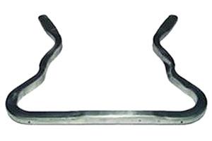
Cycle Time. A one-piece, U-shaped engine cradle, conceptually similar to the one shown in Figure 5, is formed with HPH. Made from 240 megapascals (MPa) (about 35,000 pounds per square inch [PSI]) boron steel, it is 1,005 millimeters long and 780 millimeters wide, and is fashioned from 70-millimeter-diameter tubing with a 2-millimeter wall thickness. It is produced in a cycle time of about 36 seconds.
 |
| Figure 5 Production cycle time for the engine cradle shown here is less than 22 seconds using pressure-sequence hydroforming. |
Dimensional Stability. Two ways of discussing dimensional stability that must be clearly distinguished are:
1. Width of a cross section
2. Surface location relative to the theoretical computer-aided design (CAD) model at different points along the part.
The first shows high repeatability, since springback has a smaller effect in the cross section. However, it is only part of total variation. In one test, a four-piece sample of this part had a variation range of 0.35 millimeters. A 30-piece sample over a long period of time (perhaps six months) would have substantial variation, probably more than 0.7 millimeter.
The second provides a more "real" view of how all sources of variation affect the part when it sits on data pads. The four-piece sample shows that the widest deviation is 0.65 millimeters from 10 locations on the top surface.
The Process Itself. A conceptually different step to prevent pinching and allow forming of more complex parts applies appropriate lower internal pressure while the die is closing and higher pressure after the die is closed.
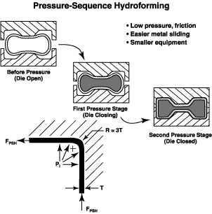 |
| Figure 6 The steps and benefits of pressure-sequence hydroforming are displayed here. |
Varying low pressure during die closing makes the fluid-filled tube act as a semi-solid and forms the part by supporting the tube wall on the inside while the cavity surface defines the outside. The tube wall is forced into the corners as the die closes, because the cavity is designed to be nearly the same periphery as the start tube. The tube wall, which is not stretched or thinned, fills the die cavity as shown in Figure 6.
This compressive force, combined with low pressure, makes it easier for metal to overcome friction and move over the cavity surface without lubricants, making very high pressures unnecessary.
When the die is closed, higher pressure is required to complete forming the tube walls. Holes then are pierced by punches mounted in the forming die. Lubricants are not applied, nor are they advantageous in PSH.
PSH hydroforming fluid provides limited rust prevention. The highest pressure used to finish forming the part can be whatever is required (for example, 172+ MPA, or 25,000 PSI).
The PSH method can apply high pressure when it is needed, such as in expansion without end feeding. However, it requires bigger and more expensive equipment and somewhat longer cycle times. All possible ways to create a part feature should be explored to find the most economical solution. High pressure should be used only when it is the best alternative and justifies the extra cost.
Normal high pressure for PSH is 34 to 69 MPA (5,000 to 10,000 PSI). Using high-strength material, thicker walls, and sharp (3T) corners has minimal impact on required pressure.
Figure 6 shows that forming the tube causes the material to yield by bending from the starting round to a finished shape of flat areas and forms sharper corners along its whole length. This nearly eliminates springback of the cross section and dimensionally stabilizes the whole part.
Part features. In this author's opinion, the range of features in PSH is potentially even wider than for HPH. All of the available elongation for a particular material can be used to form the part rather than using a portion of it to avoid pinching. If a part can be bent, it can be pressure-sequence hydroformed.
Elongation needed for hydroforming is relatively low. In production, joint-free parts with bends up to 120 degrees and bend radii down to 1.5D can be formed, while other methods may require joining two or more parts. Fewer parts and joints tend to reduce cost, weight, and dimensional variability.
Additional operations, if any, are minimized, and the problems caused by making the cavity bigger than the start tube are avoided.
Local severe deformation can be built into a part to fit with another part, to avoid interfering with it, or to form a feature that causes a die lock condition. An actuator forms the feature when the die is closed.
Pressure sequencing is less demanding on material formability. It is designed to allow use of materials specified by the customer for best part function and economy, with no need to tailor the material properties to suit the process. This allows the use of mild steel, stainless, HSLA, and galvanized steel, high-strength lower-elongation material, and aluminum.
Yield strength increases 5 to 7 percent with PSH for mild steel, similar to that achieved by HPH. The whole cross section yields, bending to form the finished shape from the starting round.
N-value, a feature critical to HPH success, is of little concern with PSH, which in normal steel- or tube-making is not watched closely.
Die Considerations. PSH dies are finished to normal die standards. Some have run up to two million parts, with no die surface refurbishment or wear inserts needed.
Hole changes can be easier and less expensive than those for stampings. Hole punching capability is well-developed in the PSH system. Hole sizes in production range from 3.1 millimeter (0.122 inches) diameter to a 40- by 45- millimeter (1.575- by 1.772-inch) rectangular slot.
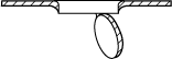 |
| Figure 7: Holes punched in the fashion illustrated here are used for numerous applications, like self-tapping screws, clips, and pins. |
At one company, more than 100 million holes currently are punched every year, with as many as 57 holes in one die. These numbers reflect customer need, not limitations. Holes are used for self-tapping screws, clips, pins, drainage, access, and other applications (see Figure 7).
Lower internal pressures increase the hole count in the hydroforming die because punch cylinders can be smaller and the die strength needed to resist pressure lower.
Equipment. Factors such as corner sharpness, material strength, and thickness that increase HPH equipment size requirements make little difference for PSH. With the PSH process, forming the same part requires about 20 to 30 percent of the internal pressure and equipment needed for HPH. Large end-feed cylinders are not required except for expanded sections.
Section Expansion Before and During Hydroforming. Figure 8 shows 15 percent tube expansion without end feeding during normal pressure sequencing using less than 48 MPA (7,000 PSI). Expansion with end feed modifies the process pressure curve to minimize wall thinning with 55 MPA (8,000 PSI).
Mechanically expanding the round tube after bending and before hydroforming thins the wall (7 percent for 41 percent expansion) less than does hydroexpansion in the die (14 percent for 41 percent expansion), because friction aids end feeding in the first situation rather than resisting it, as in the second.
Cycle Time. Production cycle time for the engine cradle shown in Figure 5 is less than 22 seconds, including handling and forming. The 35 percent lower cycle time allows 55 percent higher production capacity from one production line.
PSH offers the following benefits:
Some benefits of HPH are:
Many parts can be formed by either process. Developing an informed analysis is the only route to the more beneficial method for each part.

The Tube and Pipe Journal became the first magazine dedicated to serving the metal tube and pipe industry in 1990. Today, it remains the only North American publication devoted to this industry, and it has become the most trusted source of information for tube and pipe professionals.
start your free subscription
Easily access valuable industry resources now with full access to the digital edition of The Fabricator.

Easily access valuable industry resources now with full access to the digital edition of The Welder.

Easily access valuable industry resources now with full access to the digital edition of The Tube and Pipe Journal.

Easily access valuable industry resources now with full access to the digital edition of The Fabricator en Español.
In this episode of The Fabricator Podcast, Caleb Chamberlain, co-founder and CEO of OSH Cut, discusses his company’s...


