


Marketing Manager
Figure 1Free-form nesting allows a fabricator to fit as many parts as possible on one sheet.
Imagine this: You have a race car with the leanest, lightest chassis available and the world's fastest engine powering the vehicle, but instead of proper tires you have wheels from a shopping cart. In short, you aren't going anywhere fast.
The same analogy applies to the relationship between a CNC machine tool and the software that programs it. More specifically, the requirements placed on the software will change dramatically based on the machine technology in use—now and in the future. So what should you be looking for in a CAM system, and how can it improve the efficiency of your machine, your work force, and your material utilization?
CAM systems are used to take electronic part drawings (CAD files), process and nest them onto sheets or rolls of material, and convert the resulting nesting layouts to a series of coordinates and machining instructions. The resulting CNC programs, which ensure the part can be accurately and effectively fabricated on a specific machine tool, are then sent to the machine tools electronically. These CNC programs are very specific to each particular CNC machine technology and machine controller.
Before creating a CNC program, you have to take several steps. The job likely starts with defining (drawing) component geometry if CAD is being used or with importing component geometry, which was created in an external CAD or unfolding software.
Once the correct component geometry is available within the CAM system, tooling and profiling or cutting information needs to be added. Depending on the CAM system in use, this can be done interactively, automatically, or in some combination of both. This information differs from machine to machine and across machine tool technologies in use.
Once all of the manufacturing information has been applied to components, the next task is to nest them—squeezing as many components on the sheet or a roll as possible (see Figure 1). A nest might consist of the same parts or a mixture of different parts and can be classified as either rectangular or free-form.
Rectangular nesting positions each component as if it were a rectangle, which will result in a significant waste of material if you are cutting many irregular shapes. With rectangular nesting, parts may be nested at different angles, but are usually nested at 0 and 90 degrees.
Free-form nesting offers the best material yield because it nests parts at any angle and also takes advantage of any scrap material within larger components, such as cutouts.
Depending on a CAM system's level of automation, the placement of parts will be manual, automatic, or a combination of both processes. Manual nesting of dissimilar components is often performed by dragging and dropping parts on the nest, also known as bump nesting. Unless you are very skilled, this process can result in significant material waste and, in any case, is invariably a very slow process. Because of this, many companies currently produce so-called static nests, which are created manually and are regularly reused. The problem with this is that all of the parts will be produced each time a particular nest is run on the machine, regardless of whether they are all needed.
Dynamic automatic nesting, on the other hand, allows for unique nests to be created when required, providing a just-in-time approach while achieving high material usage. This is especially important when processing expensive materials.
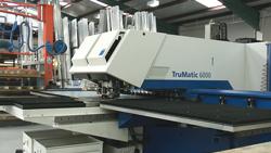
Figure 2A combination laser cutting/punching machine represents just one more programming challenge for today's CAM software packages.
Other considerations for CAM software should include:
Additionally, some systems will "learn" the preferred tool placement settings, quickly becoming self-sufficient.
At this point we have all of the cutting information applied to the nest; however, one more important consideration has a significant impact on the cutting time—the sequence in which these instructions are processed. Sequencing can be either an interactive or automatic process.
Programmers often want to simulate the job before running it on the machine. On a capable CAM system, simulation shows exactly what will happen when the nest is run on the machine tool. A lot of time and money can be saved by graphically simulating the fabricating process and identifying possible problems, such as a component being cut, punched, or unloaded incorrectly or in the wrong sequence. Simulation gives the CNC programmer a great deal of confidence, ensuring that when the operator presses the start button on the machine tool, he is not going to have any major disasters.
Once the simulation is satisfactory, a CNC program for the machine can be generated. A special module in the CAM system normally tackles this function. It takes the generic machining data stored in the CAM system's database for a particular nest and converts it to CNC program instructions a particular machine tool will "understand." This is referred to as postprocessing, and the module is usually called the postprocessor, regardless of whether it is an internal or external function to the CAM system.
Just about every machine tool requires different instructions, and to complicate the matter still further, each machine tool can offer a range of options, such as complex loading/unloading systems, tapping attachments, and labeling devices. Additionally, combination machines (see Figure 2) that combine two or even three different fabricating technologies in one machine tool, such as a punch/laser or punch/right-angle shear, also can have options.
When you purchase a CAM system from an independent vendor, you will choose a postprocessor to match your machine. This is actually one of the most important aspects of a CAM system, because without a well-constructed postprocessor, you will not get the best out of your machine.
A postprocessor can be compared to a printer driver—it takes a printed document and converts it to something that your printer can understand and produce. Ask the software vendor for details about existing customers that have the same machine tool, so that you can find out their experiences. If the machine is new and no postprocessor exists, you probably will need to supply the machine programming manual and other information to the CAM vendor to help them to develop the required postprocessor for you.
Now that you understand what CAM software does and what it can accomplish, let's talk about things to keep in mind before investing in a new package.
A new machine tool is nothing more than an expensive paper weight if you cannot feed it fast enough with reliable CNC programs. Most machine tool builders offer some sort of CNC programming system with their machines. These might come from independent software vendors or may be developed by the machine manufacturer. The ones developed by machine manufacturers usually support only their machine tools. Keep in mind that if you acquire such a CAM system and you decide to buy another machine tool from another manufacturer in the future, your CAM system will not be compatible with it. You will need another one to program the new machine. In any case, it is always a good idea to compare offerings from a variety of CAM system vendors when purchasing a machine tool.

Figure 3One software license might be enough for small fabricating operations, but larger shops might need more. Some vendors offer floating licenses, which allow a set number of users to work with the system simultaneously.
The software's functionality and automation will determine its price. It is a fact that, although CAM systems affect numerous areas of the business, many companies make the mistake of tasking the selection of CAM software to the CNC programming department alone. Ideally, it should have sponsorship and final expenditure signoff at the executive level, people who should understand the potential impact of it on the whole operation.
Which CAM system you should select depends very much on your company's operation, machine tools in use, and the quantities and mix of parts being produced. The materials you process and their prices also figure strongly in this evaluation.
Numerous CAM systems offering various levels of functionality are available worldwide, but only a few offer a range of levels from the fairly simple and inexpensive to full automation.
If you decide that your organization currently has no need for high functionality and automation and select an entry-level CAM system, make sure that it will grow with you. You may have only one simple machine tool today with limited programming needs, but in a year or two the situation may change, and you suddenly may realize that you need to program another machine or two that you just acquired.
At that time you may decide that as your material usage increases, you want the most effective automatic nesting to cash in on potential material savings. Because of this, you want to make sure that the CAM system you select now can be upgraded to higher levels of functionality and automation and that it can effectively support any machine tool you may purchase in the future.
More specifically, here are some questions to ask:
1. How many machine tools need to be programmed? Will one or two seats, or licenses (see Figure 3), of the CAM software be sufficient to program the machines, or are more needed? (The answer to this question very much depends on the level of automation and functionality you select for your new CAM system, but remember that more licenses also require more personnel to operate them.)
2. Should existing CAM systems programming other machines be replaced to consolidate programming of all machine tools into one system?
3. Does the vendor have postprocessors for all of our machines, and if not, are they capable of developing the ones they do not have?
4. How easy is it to get information in and out of the system, such as CAD files and reports?
5. If we need more than one software license, do we need them to all run concurrently? (Some vendors offer floating licenses, which allow a set number of users to work with the system simultaneously.)
6. What type of parts will be nested? Is automatic nesting desired, and if so, does rectangular or free-form make sense? How important is nesting efficiency? Will we cut expensive materials now or in the future?
7. How much automation is required? Can the CAM system be integrated with our front-office shop management systems, such as materials resource planning (MRP) software? Can the MRP system supply the CAM system with component orders automatically? Can the CAM system receive such automatic ordering and report current status back to MRP? Will the CAM system be expected to run and execute component orders and program machines unattended?
lthough you may have a list of features that you know you definitely will need in the new CAM package, do not get too bogged down in creating a features list. Concentrate on the end goal—accurate and efficient CNC programs to drive your machines with the minimum amount of effort required.
So how do you quantify that? The key to an effective evaluation process can be found by scrutinizing three areas: staff time, covering programming, reporting, and anything else related to the CAM process; machine cycle time (also referred to as run time); and material utilization.
These three areas can be reported in quantifiable costs. Before you even consider evaluating CAM systems, you need to understand what those costs currently are.
Labor-hours generally are simple enough to cost, as are machine run times and costs. However, it is always a worthwhile exercise to follow a few jobs through all processes and note all costs associated with them. Material efficiency is not much more difficult to calculate if you look at it in terms of waste rather than output. Once you have a clear understanding of all the above, you are ready to move on to the next stage—the benchmark comparison.
By now you should have a clearer idea of what you need, so it's time to start investigating the market. Recommendations should carry more weight, especially if they come from users that have the same machines as you are considering.
Once you have selected your vendors, you need to arrange for a benchmark comparison. Provide each vendor with a series of parts in the form of DXF or IGES files, along with tooling and nesting parameters, and ask them to perform the following:
It is important to check and recheck the figures that you are provided with. Check to ensure that no parts are overlapping on the nest or that they have not been rescaled slightly to fit a particularly complex nest. Check gaps between components and components and material edges. Because each machine generally is uniquely configured, it probably will not be possible for them to provide you with resulting CNC programs to check machine run time.
In addition to the savings that you can tally up, other benefits that might not be so easy to spot may exist. For example, more efficient nesting and the ability to produce complex dynamic nests quickly might allow you to standardize on fewer material sizes.
Once you have your set of figures, it is then a simple process of adding them up and comparing old versus new. Take the difference and divide it by 52 (or your company's number of working weeks). You now know to the week when your CAM system will have paid for itself.
Some CAM systems simply take component geometries, nest them, and apply tooling or cutting at the nest level. Such a system cannot retain any information regarding fabricating of individual components, which means that any manufacturing information added or modified on a particular component exists only on that particular nest. If a programmer needs to nest that same component sometime in the future, that same fabricating information will have to be added or modified manually again.
On the other hand, some CAM systems can store a component's fabricating information in a component file together with component geometry. However, a separate component file may be required for each machine the component is made on, and sometimes even for each different angular position of the component on a nest. This complicates matters quite a bit, as any revision of the component geometry or tooling may force modifications of many similar files. However, as the fabricating information is stored together with a particular component geometry, the programmer does not need to re-enter any of it when the component needs to be nested again.
Highly capable CAM systems use a combination of both methods to achieve the most efficient machine programming system, storing geometry and fabricating information in a single component file. In such systems, once programmed (either manually or automatically), a component file stores all important fabricating information for any angular position in a nest and for any number of machines you may be operating.
You also should be aware of CAM software issues outside of the actual features and capabilities of the product. How much time, consultation, and effort will be required to install and satisfactorily implement the CAM system? How much training is required before the CNC department is sufficiently proficient? How difficult is software update implementation? Will new updates be fully compatible with all work files, technology databases, and settings regardless of which version you are updating?
Reliable answers to many of these questions can be obtained only from existing users. So ask for references and talk to them. It may save you a lot of grief in the future.

The Fabricator is North America's leading magazine for the metal forming and fabricating industry. The magazine delivers the news, technical articles, and case histories that enable fabricators to do their jobs more efficiently. The Fabricator has served the industry since 1970.
start your free subscription
Easily access valuable industry resources now with full access to the digital edition of The Fabricator.

Easily access valuable industry resources now with full access to the digital edition of The Welder.

Easily access valuable industry resources now with full access to the digital edition of The Tube and Pipe Journal.

Easily access valuable industry resources now with full access to the digital edition of The Fabricator en Español.
In this episode of The Fabricator Podcast, Caleb Chamberlain, co-founder and CEO of OSH Cut, discusses his company’s...


