


Pushing the solid-state laser speed limit
How to realize the technology’s awe-inspiring potential
Editor’s Note: This article is based on “High-speed cutting with lasers,” a presentation by Dr. Andreas Wetzig, head of the Laser Ablation and Cutting Department at the Fraunhofer Institute for Material and Beam Technology, Dresden, Germany, www.iws.fraunhofer.de. It was presented at the 2014 Advanced Laser Applications Workshop (ALAW®), Plymouth, Mich., organized by the Fabricators & Manufacturers Association International®, www.fmanet.org, www.alawlaser.org.
In the early days of laser cutting, the machine had no trouble keeping up with the capabilities of the beam. A low-powered CO2 laser could cut only so fast without creating problems with edge quality and incomplete penetration. The basic Cartesian positioning system, driven by a ball screw, crept along. Back then the mere fact that light could blank out a sheet metal part, without a hard tool, was enough to make economic sense.
High-brightness solid-state lasers have reversed the situation. These 1-micron-wavelength beams have extremely high energy densities, and they can be absorbed so effectively by thin sheet metal that the beam’s ability to cut is no longer the constraint. Now it is the machine that needs to catch up with the beam in thin-sheet applications.
Admittedly this can be difficult to fathom, considering just how fast modern machines move their processing heads. Advanced motion systems with direct-drive technology cut holes in what seems like a flash, at least relative to earlier laser cutting systems. Still, if a job called for just a straight-line cut, theoretically a high-brightness solid-state laser beam could cut extraordinarily quickly, particularly on thin sheet metal, close to 1,000 meters a minute. At that speed the cutting would look nearly instantaneous.
Of course, no machine in the world can drive a laser this quickly. Moreover, to cut complex shapes, a traditional Cartesian motion system has no choice but to slow down. Consider a typical gasket made of 304 stainless steel, with a circular outside diameter and an inside diameter that includes complex contours, with many 90-degree corners. If all cuts were just a straight line, a 4-kW solid-state laser could cut 1-mm-thick material at more than 50m/min. But the reality is that the head moves between 5 and 15 m/min. to cut the inside contours, then jumps to 30 m/min. to cut the outside contour.
The machine tool industry continues to work toward solutions, and two distinct approaches show promise. One uses additional axes within the processing head itself, and the other—for extremely thin material—eliminates the entire nozzle and cutting head assembly altogether.
Additional Axes
A typical laser cutting machine uses a stiff bridge to manipulate the cutting head assembly, but it requires a lot of energy to move. A large object in motion takes a lot of energy to decelerate, change direction, and accelerate again. In physics, these changes in the rate of acceleration are called jerk, and the faster the jerk, the less time the processing head spends slowing down and speeding up again when it changes direction.
So what’s the solution? It again goes back to physics: Reduce the masses involved, and develop a way to make a system more dynamic so that it takes less energy to accelerate and change direction. Several technologies have been available to overcome this for several years, and one is high-dynamic local axes. Here, not only does the processing head assembly move in the X and Y directions, but so does the nozzle itself, independent of the main axis. Both the cutting head and nozzle moves are synchronized to create the fastest cutting environment possible (see Figures 1 and 2).
Imagine a cutting head that needs to cut a cross-shaped part. If that cutting head sits on a standard Cartesian system, it has no choice but to slow to a stop (albeit very briefly) to cut the corners. There’s really no way to avoid this, unless you alter the traditional X-Y Cartesian system, and this is exactly what some of the latest machine tool designs have done—specifically, by superposing another X and Y axes on the cutting nozzle itself.
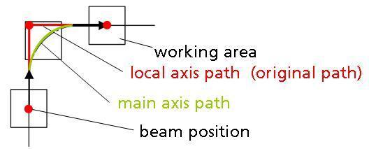
Imagine the same cross application, only now the processing head need not move to every corner. Instead, it follows a curved path, meaning it avoids stopping to make the hard turn at the corner. Meanwhile, synchronized axes in the nozzle itself move out to cut the corners (see Figure 3).
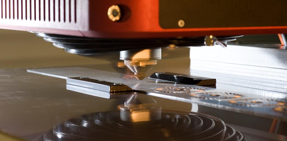
Figure 1
In this laser cutting setup, not only does the processing head assembly move in X and Y, but so does the
nozzle itself, independent of the main axis.
At the system’s heart are complex algorithms that coordinate the motion of the main axes with the superposed axes at the nozzle. Algorithms also guide the lenses and other elements inside the processing head so that when the nozzle moves, the beam moves with it.
This approach has been shown to reduce cutting time by more than half, depending on the application. This doesn’t push the solid-state laser’s thin-sheet cutting speed all the way to its theoretical maximum, but it certainly gets it much closer.
Remote Laser Beam Cutting
Systems with superposing axes approach the problem by altering existing technologies to push the beam faster. The real constraint in the whole system, though, is the nozzle itself. Considering this, is it possible to cut metal without one? To make this feasible, you need to consider that there’s more than one way to make a kerf.
In most conventional applications, the laser beam melts the metal; in carbon steel, the heat causes an exothermic reaction with oxygen to aid the cutting. But in all materials, it’s the assist gas flowing through the nozzle that evacuates that material to create the kerf.
However, laser technology has evolved to the point where in certain circumstances, the nozzle and hence the assist gas may not be necessary to cut sheet metal. Here is where a somewhat new process comes into the picture: remote laser cutting.
To understand its potential, consider a different but more mature technology: remote laser beam welding. Here, the beam focal length is measured in feet or meters, and this innovation opens up a realm of possibilities. No longer does a welding head need to move great distances between weld seams. That’s because in remote laser welding, the head isn’t positioned only millimeters from the workpiece surface. Instead, a workpiece is fixtured under a laser head several feet above, and in a matter of microseconds, scanning mirrors send the beam from one weld location to the next.
If this could be applied to cutting, it would have significant implications. No longer would you need to deal with the inertia of large moving masses (that is, the cutting head). Instead, scanning optics could move the beam to the solid-state laser beam’s full potential.
Of course, one large hurdle remains: Without that jet of assist gas coming from the nozzle, how do you remove the molten material from the kerf? From a broad perspective, any laser cutting process must somehow remove the kerf material.
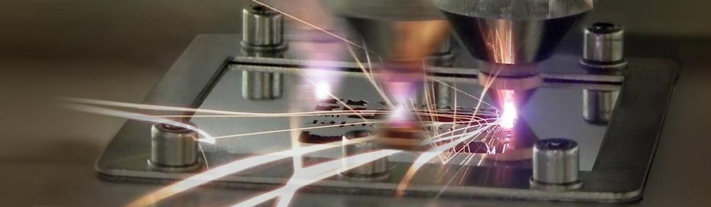
To address this, several remote laser cutting technologies have emerged, and they all use the high-energy-density characteristics of the solid-state laser beam. When it comes to laser cutting at high speeds, one remote cutting process shows particular promise in very thin material. The technology creates the kerf not by evacuating molten metal with assist gas, but instead by ablating it—that is, vaporizing the metal.
For years high-peak-power pulsed lasers have been used to ablate holes in microcutting applications, though this is a relatively slow process. But recently the extraordinarily high energy densities possible in modern solid-state lasers have expanded the possibilities, and this includes flat-sheet cutting. The technology uses the gas pressure from metal vaporization to remove material from the cutting kerf. In effect, the beam ablates the material, layer by layer. Note also that some applications require shielding gas, but many do not.
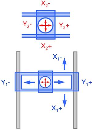
Figure 2
Like on conventional flatbed lasers, the cutting
head rides on a gantry and moves in the X and Y direction.
But here the nozzle also moves on its own local
X-Y axes.
Ablation requires extreme energy concentration, and this is where the single-mode fiber laser comes into play. Single-mode solid-state lasers produce a highly intense beam that can be focused down to a small spot size. The energy is so intense that most of the exposed workpiece material vaporizes (see Figure 4).
Today this process shows tremendous potential in very thin material, including steel foils. A 1-kW, single-mode solid-state laser can ablate 30-micron-thick foil (0.03 mm) in a single pass, producing an effective cutting speed of almost 1,000 m/min.
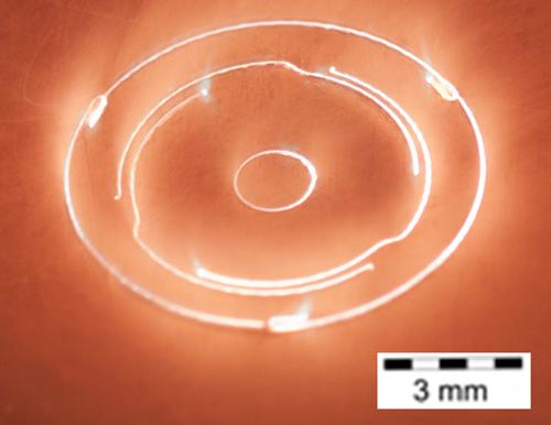
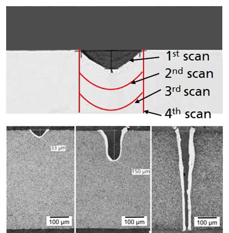
If you’re working with extremely thin foils, between 0.01 and 0.04 mm thick, the laser can ablate a kerf in one pass. But for thicker materials, the laser needs to make multiple passes to create a kerf (see Figure 5).
At present most who are considering remote laser beam cutting use 0.5 mm as a benchmark. At that material thickness, a 1-kW, single-mode laser can cut at about 100 m/min. It’s technically feasible to cut thicker materials: The process has been tested to cut material that’s a little less than 1 mm at nearly 100m/min., but for an acceptable cycle time, the laser needs to remove a significant amount of material with each pass. That in turn requires the extreme power density provided by a 3- or even 5-kW, single-mode solid-state laser, a cost that needs to be taken into account.
Theoretically, the process could cut materials thicker than 1 mm, but at some point, because the laser needs to take so many passes, it becomes slower than conventional cutting with a flatbed laser.
Still, for the right application, cycle time reductions can be dramatic. Applications include complex gaskets, spring elements, and components for fuel cells. As just one example, a manufacturer of exhaust gaskets once used conventional laser cutting, and to cut one gasket took the laser 3.1 seconds; the remote laser cutting process used today finishes the job in 0.3 second.
Different Technologies, Same Problem
Superposing additional axes and remote laser beam cutting are two very different technologies. Still, both help push the solid-state laser closer to its full potential. Additional axes make the acceleration and deceleration phases of the cutting cycle more efficient, while remote laser beam cutting virtually eliminates acceleration and deceleration entirely.
In thicker materials, the beam itself remains the constraint. A conventional flatbed laser cutting machine could drive the cutting head at a greater speed, but the beam just can’t cut through plate any faster. But in thin material, the roles reverse. The beam could cut much faster; it’s the drive system that’s holding it back.
Technology is evolving to rectify this problem. No one can say where laser technology will be a decade from now, but the current state-of-the-art continues to push the laser cutting speed limit.
About the Publication

subscribe now

The Fabricator is North America's leading magazine for the metal forming and fabricating industry. The magazine delivers the news, technical articles, and case histories that enable fabricators to do their jobs more efficiently. The Fabricator has served the industry since 1970.
start your free subscription- Stay connected from anywhere

Easily access valuable industry resources now with full access to the digital edition of The Fabricator.

Easily access valuable industry resources now with full access to the digital edition of The Welder.

Easily access valuable industry resources now with full access to the digital edition of The Tube and Pipe Journal.

Easily access valuable industry resources now with full access to the digital edition of The Fabricator en Español.
- Podcasting

In this episode of The Fabricator Podcast, Caleb Chamberlain, co-founder and CEO of OSH Cut, discusses his company’s...


