


Senior Editor
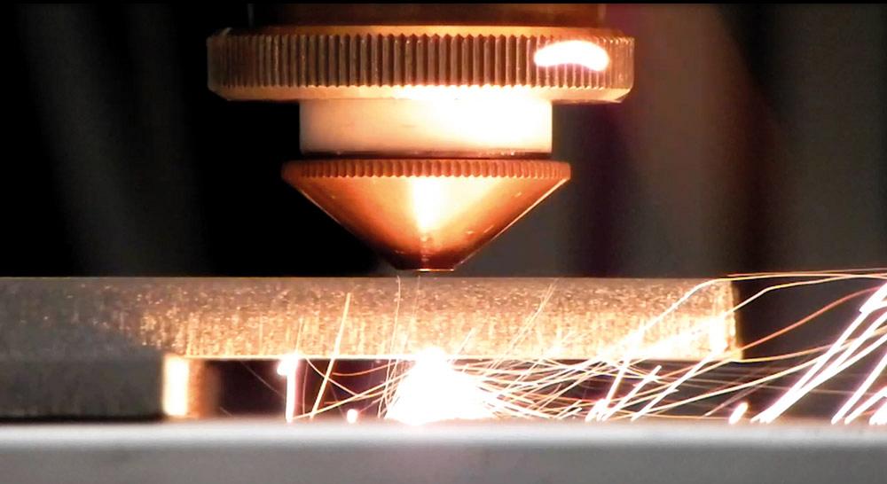
The galvanometer has a long history with the laser. Also called galvoscanners, galvopositioners, or simply galvos, they can move the laser beam nearly instantaneously from one point to another. Laser light shows wouldn’t exist without them. Neither would most types of laser marking. Remote laser beam welding relies on them, as does emerging remote laser beam cutting technology.
In the future, some critical sheet metal and plate cutting applications may rely on a galvo to manipulate the laser beam in just the right way to produce the best cutting edge. This comes from ongoing work at the Fraunhofer Institute in Dresden, Germany, where photonics researchers are focusing not only on the beam quality and profile, but also how exactly that beam moves in the cut.
Although it looks complicated, the recipe for a smooth laser-cut edge doesn’t have too many ingredients. You have the assist gas, be it oxygen or nitrogen. Then you have the beam itself.
This includes the beam’s absorption characteristics, or how well a particular material absorbs a particular laser wavelength.
Of course, the most finely tuned laser beam in the world wouldn’t be effective if it weren’t moved to the right position quickly and precisely. But simply “moving” the laser beam involves more than finding the best path from point A to point B. Along the cutting or welding path, could the laser beam be moved in such a way as to increase quality and efficiency? Here, the galvo may play an increasing role.
“A galvo system consists of three main components: the motor or galvanometer, the mirror or mirrors, and the servo—the driver board that controls the system.” So wrote Contributing Editor Valerie Coffey in Laser Focus World.
As she described, the servo drives the galvanometer, which, using the properties of electromagnetism, manipulates the mirror. These components make up what are known as scanning optics.
Scanning optics have become a central component of laser marking, laser welding, and even certain laser cutting applications. In remote laser beam welding, where the beam focal length is measured in feet or meters, scanning optics send the beam from one weld to the next in a matter of microseconds.
Most recently, scanning optics have directed a beam to cut (or, more accurately, ablate) very thin material, usually 0.5 mm or less. Developed at Fraunhofer, the laser moves nearly instantaneously to ablate, or vaporize, material in the kerf. If you’re working with extremely thin foils, between 0.01 and 0.10 mm, the laser can ablate a kerf in one pass; for thicker workpieces, the laser beam needs to take multiple passes. Regardless, to the naked eye, the scanning optics drive the laser so quickly, the cutting can look virtually instantaneous.
Without a cutting head nozzle close to the workpiece, remote laser beam cutting can’t make use of assist gas to evacuate molten material; it relies on ablation to create the kerf. This makes the process impractical for most materials thicker than 0.5 mm.
Considering this, you might think that laser scanning optics would have limited use for thicker material. But back in 2008, Fraunhofer researchers thought otherwise.
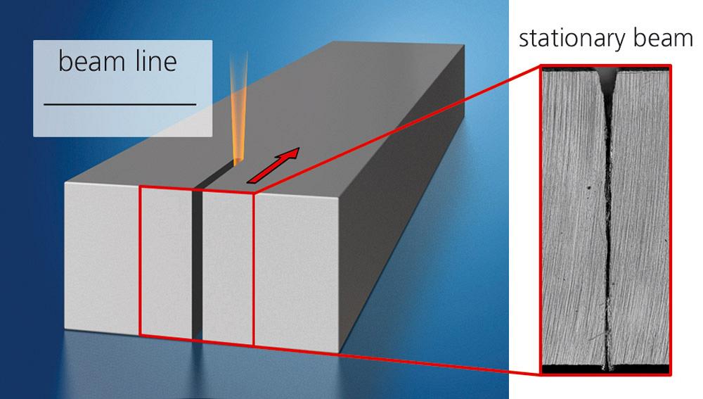
Figure 1
A non-oscillating laser beam cutting in thick stainless leaves an edge that may require extra finishing.
A machinist’s toolroom has milling and turning tools of myriad shapes and sizes. Each tooling component, both of the tool body and of the number and orientation of cutting inserts, works better in some machining operations and worse in others, depending on the geometries being cut and the workpiece at hand.
In the sheet metal laser cutting arena, technicians do change the focus and (on some machines) the beam diameter to achieve the best cutting edge. But unlike a machinist choosing a cutting tool, laser technicians in typical sheet and plate laser cutting operations can’t significantly change the shape of the beam.
For years the industry has worked to manipulate the beam characteristics to better suit a specific application. But in 2008, some researchers at Fraunhofer started focusing not on the laser beam characteristics, but instead on how that beam could be moved with scanning optics. Such optics already were being used to move the beam great distances very quickly, but could they oscillate the beam in tiny patterns in the cut or weld path itself? If they could oscillate the beam fast enough in a small pattern, would the new “shape” of the beam improve processing characteristics?
It turns out that it does, at least for some applications that by now have undergone years of testing. Fraunhofer calls this technology dynamic beam shaping.
The quest began in 2008 with CO2 lasers. Researchers at Fraunhofer placed high-speed galvos just before the focusing lens, thinking that oscillating the beam in specific patterns would modify the angle of the cutting front when laser cutting thick stainless steel (see Figures 1 and 2).
“We were able to reduce the surface roughness of the cut edge, reduce dross, and, if we chose the right parameters, we even could increase the cutting speed,” said Andreas Wetzig, head of the Laser Ablation and Cutting Department at the Fraunhofer Institute for Material and Beam Technology in Dresden.
About four years ago experimental work began on integrating dynamic beam shaping on fiber lasers. In these setups, researchers placed galvos inside the cutting head, between the beam collimator and the focusing optic. Recently they have also used different laser power sources.
“We aren’t manipulating the beam characteristics in any way,” Wetzig said. “We are basically just moving the beam very fast, and we have many degrees of freedom. We can modify the frequency of oscillation. We can move the beam backward and forward, parallel to the cutting direction, and we can oscillate the beam perpendicular to the cutting direction.
“Note that the amplitude of the mirror is actually very small, compared to conventional applications of galvo-heads,” Wetzig continued. He added that although the system uses a modified galvo-head designed to move the beam in small, tight patterns, all other components in the system—the collimator, the focusing lens, and the cover slide—are conventional, off-the-shelf items. Researchers also have used conventional nozzles for nitrogen assist gas. (As of yet, they haven’t tackled oxygen cutting of carbon steel.)
The galvos gave researchers the freedom to experiment with numerous patterns, including circles, ovals, and crescent shapes. In the end, they found that a figure-eight pattern, perpendicular to the cut direction, tended to work best for cutting thick stainless steel (see Figures 3 and 4).
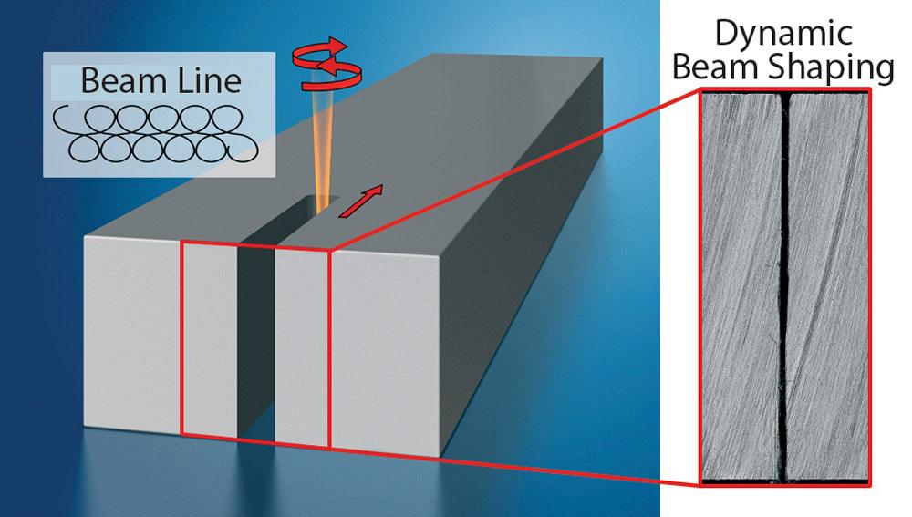
Figure 2
An oscillating beam in thick material creates a kerf with clean edges.
Another benefit: The oscillation allows operators to optimize one cutting lens for various material thicknesses and grades. “Wobbling the beam has the same effect as using another lens for a longer focal length,” Wetzig said.
The greatest development challenge wasn’t necessarily in the galvos themselves, but in the control software that manages communication between the beam-shaping galvos and the controller. The oscillation must change with the shape of the cut. The figure-eight pattern remains perpendicular to the kerf as long as the cut is straight, but what about curves and corners?
The galvo needs to move the figure-eight-pattern oscillation to keep the pattern perpendicular to the cutting direction, even as that cutting direction changes. Complicated patterns with a lot of curves and contours require constant communication between the galvo and the controller.
Fraunhofer researchers also have been experimenting with beam oscillation in laser welding, particularly for challenging applications like dissimilar-material joining, such as copper to aluminum and aluminum to cast aluminum.
At present the technology does have a few limitations. First, the galvo system works reliably only with laser powers up to 4 kW. Above that, the galvos can’t handle the intense energy from the laser beam. Second, galvos can oscillate the beam up to 4 kHz—though to be clear, Wetzig said that, depending on the application, going faster than 4 kHz may not make a difference in resulting quality. “In fact, so far we’ve gotten our best results when oscillating the beam between 2 and 3 kHz.”
Still, traditional galvos may not be the only option for dynamic beam shaping. A separate research team at Fraunhofer is now using what’s known as a MEMS, or a micro-electro-mechanical scanner. Basically, a MEMS involves building the scanning mechanism into the mirror itself. MEMS technology has been used for, among other things, the heads-up windshield displays seen on high-end cars.
“By using this technology, we can achieve higher [oscillating] frequencies,” Wetzig explained. “On the other hand, it is limited, because the frequency is fixed based on the mechanical design of the mirror.”
A MEMS system can oscillate the beam all the way up to 20 kHz, which may be advantageous for some applications. But once that mirror is designed to oscillate at a specific frequency, it can’t be changed.
At this point Wetzig said that dynamic beam shaping technology still is being developed for specific high-end applications, mainly cutting thick stainless steel with nitrogen—critical work involving expensive material
that previously may have needed to be machined to achieve the desired edge quality.
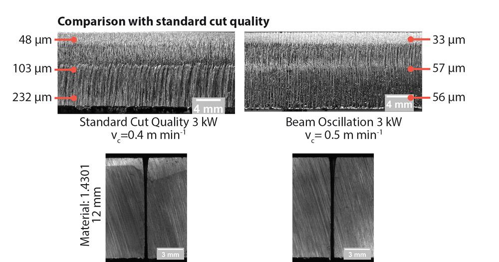
Figure 3
A cut made with a non-oscillating 3-kW beam in 12-mm-thick stainless shows striations, on the left. Roughness is measured in Rz values, or the mean roughness depth.
“I see some of the greatest potential in laser welding dissimilar materials, and for laser cutting of critical material,” Wetzig said. “Again, [the beam oscillation] makes it a more forgiving process, and you can use one focusing lens for thin and thick material.”
Wetzig added that the research team has yet to develop a “recipe” for specific material thicknesses and grades, which refers to the specific laser and cutting head properties. For instance, if an operator needs to cut a specific thickness of stainless, he can’t refer to a chart that shows him the optimal oscillation shape and frequency for the job. For now there are just too many variables, including the cutting path contour and, of course, the material quality, which can change from batch to batch.
“The usage of DOE [design of experiment] strategies and sensor-based investigation algorithms helps to minimize the efforts of finding the best parameters,” Wetzig said. “The scientist who is conducting the experiments has a good feeling about what to do; she has a plan for each setup she does. But so far the path [to standard parameter settings] is known, but not completely understood.”
Regardless, dynamic beam shaping may find a place in laser cutting and welding systems within the coming years. Wetzig said that adding a beam-shaping option on a machine may make sense if a fabricator processes materials of different grades and qualities. “If you work at a job shop and always find yourself cutting materials of varying quality, [dynamic beam shaping] may help make laser cutting be a more forgiving process,” he said.
For certain fabricators looking to differentiate themselves with high-end materials processing, shaping the beam could help make once challenging operations relatively easy, stable, and efficient.
Images provided by Fraunhofer Institute for Material and Beam Technology, Dresden, Germany, 49-351-83391-0, www.iws.fraunhofer.de.
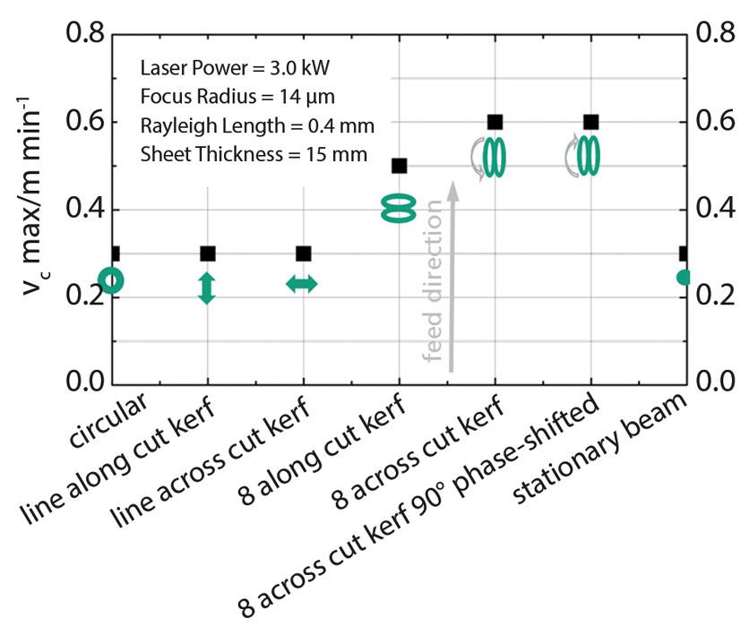
Figure 4
The dynamic beam shaping team at Fraunhofer has found the best results by oscillating the beam in a figure-eight pattern, which cleanly cut 15-mm-thick stainless steel.


The Fabricator is North America's leading magazine for the metal forming and fabricating industry. The magazine delivers the news, technical articles, and case histories that enable fabricators to do their jobs more efficiently. The Fabricator has served the industry since 1970.
start your free subscription
Easily access valuable industry resources now with full access to the digital edition of The Fabricator.

Easily access valuable industry resources now with full access to the digital edition of The Welder.

Easily access valuable industry resources now with full access to the digital edition of The Tube and Pipe Journal.

Easily access valuable industry resources now with full access to the digital edition of The Fabricator en Español.
In this podcast episode, Brian Steel, CEO of Cadrex Manufacturing, discusses the challenges of acquiring, merging, and integrating...


