


Senior Editor
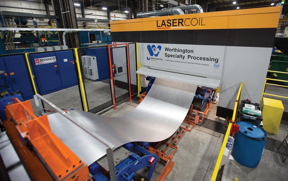
Figure 1
Earlier this year, Worthington Specialty Processing, a Michigan-based toll processor, installed a continuous-feed, coil-fed laser blanking system.
Around the turn of the millennium, people participating in a multicompany consortium had high hopes. They called themselves Laser Blanking Central, and they came from companies such as DCT in Sterling Heights, Mich., and Alabama Laser Systems in Munford, Ala. These people, along with laser experts such as Charles Caristan (now a technical fellow at Air Liquide), asked a progressive question: What if a blanking press could be replaced by a coil-fed laser cutting system?
Fast-forward to today, and we see the laser blanking concept finally picking up steam, with lines installed in Europe as well as stateside. In 2014 Precision Strip, a toll processor in Perrysburg, Ohio, installed a laser blanking line with an indexed coil feed from LaserCoil Technologies, Napoleon, Ohio. That is, the coil feeds strip into the work area; the strip remains stationary until the end of the cutting cycle, at which point more coil feeds in and the cycle repeats.
Then earlier this year, Worthington Specialty Processing (WSP), a toll processor serving the automotive industry, among others, launched a continuous-feed laser blanking system into production (see Figure 1). Now making blanks in WSP’s Jackson, Mich., plant, the coil-fed laser blanking line feeds material under two 6-kW fiber laser cutting heads. Operating in an enclosure for safety, due to their 1-micron wavelengths, the lasers cut blanks as the strip moves continuously underneath, and scrap falls underneath while several robots lift and stack the cut blanks (see Figure 2). The laser system comes from LaserCoil while the coil feeding and robotic part removal portions of the line come from LaserCoil’s affiliate company, Automatic Feed Co.
The system now processes material as thin as 0.5 mm up to about 3 mm. The high-powered fiber lasers can cut materials much thicker than this. But to maintain high speeds and ensure proper part stacking, laser blanking systems usually stick to thinner stock.
All this resembles the vision Laser Blanking Central had more than 16 years ago, and that vision has finally become reality.
In 2000 those involved in laser blanking development saw the rapid rise of laser cutting in industry during the late 1990s, particularly in lower-volume metal fabrication. As CO2 laser powers grew, so did their cutting speed, especially on stock 3 mm or less, which happens to be the thickness range used for most of the automotive body-in-white.
Then, as now, automotive companies rely primarily on the mechanical press to cut blanks that are later formed and welded as part of the car or truck body. Still, building, maintaining, and changing out blanking dies is neither cheap nor adaptable. When new car designs required a new blank, they also required a new, or at least altered, blanking die.
For years lower-volume sheet metal fabricators had been using interchangeable tools on turret or rail-type punch presses. And in the 1990s more shops began investing in laser technology. By 2000 CO2 lasers had gotten so powerful and so fast, some thought that they just might make sense in certain production environments. Instead of blanking with a stamping press, could automotive companies and their suppliers produce blanks with a coil-fed laser cutting system?
It was an elegant concept, with none of the costs associated with hard tooling: no die development, maintenance, storage, or changeover. Blanks also could be redesigned for optimal forming. It’s less expensive to machine dies with straight edges and angles, yet those straight corners present metal forming challenges. A laser, on the other hand, is just the opposite. It cuts curves quite efficiently, but to cut a corner, the laser must stop ever so briefly before moving in a new direction. Cutting a curve, the laser head moves continuously around the contour.
For years the idea struggled to catch on, not only because of challenging market conditions in the automotive industry, but also because many auto players at the time still followed a high-volume, low-mix philosophy. Model changes weren’t as frequent. Also, there were technology limitations. CO2 lasers send the beam through a series of optics and on to the cutting head. Those optics need to be maintained and kept pristine, which presents issues in a high-production environment. Plus, CO2 lasers of the day could cut only so fast.
Figure 2
At the end of the laser blanking line, robots lift and stack the cut blanks.
“Throughput is the main consideration when it comes to any manufacturing setup,” wrote laser consultant Michael Bembenek in a 2006 issue of Industrial Laser Solutions. “Speed and cycle time … are not overwhelming. This is probably why the response from blank-makers and blank users to the use of laser blanking is always the same: ‘I don’t see the economics.’”
During the ensuing years the situation changed dramatically, partly because of the push toward high-strength steels and other alternative materials. Such strong, thin materials cause blanking dies to wear quickly. But a laser doesn’t care how hard a particular material is. Using a laser, you’re cutting with light (and assist gas); how well a laser cuts depends not on the material’s strength, but on how it absorbs the energy from that light. Alternative materials can be costly, too, so a tight nest that fully utilizes the material across the width of the strip—which laser blanking can do quite well—has become more attractive than ever.
Then there’s the fiber laser and, especially, ever-advancing optics that can consistently and effectively deliver the highly powerful beam necessary for extraordinarily fast sheet metal cutting. The solid-state laser sends the beam through a delivery fiber, which connects directly to the cutting head. Integrating such a laser into a large automated system is relatively simple, at least compared to its gas laser counterpart.
Sources at WSP and LaserCoil did not disclose the speed at which the two 6-kW IPG Photonics fiber lasers can cut. They only said that in laser blanking, cutting speed is no longer a limitation.
“Our system cuts very, very fast,” said Gary Mayer, WSP’s plant superintendent.
Mayer and other sources added that inches per minute (IPM) has to be taken in context. In truth, cutting speed varies depending on the blank’s shape. Also, if more throughput is needed in the future, more laser cutting heads can be integrated into the system.
Moreover, no matter how fast the laser cuts, all that speed doesn’t mean much if scrap isn’t evacuated or parts aren’t offloaded efficiently. Here is where LaserCoil’s dynamic conveyor and material handling robots play a role.
The dynamic conveyor, as shown in Figure 3, provides open space below the kerf as it’s being cut. The conveyor consists of a series of servo-controlled flat-belt conveyor lanes that move to create a space underneath the kerf, allowing sparks and dust to fall below. From there a downdraft dust collection system evacuates the fume and floating debris and sends it to a filtration system—no gunky slats to clean, no significant impurities floating about the work envelope. The motion of those conveyor lanes also allows scrap from the skeleton to fall through (see Figure 4), while the remaining cut blanks are picked up and stacked neatly by robots with suction grippers.
“The dynamic conveyor allows everything to be clear of the laser at all times,” said Jay Finn, general manager and chief technology officer at LaserCoil. “The [conveyor lanes] provide support, but they also move to provide an opening for the kerf path, so we can cut as fast as we can and make sure we’re always clear, and everything is open underneath the laser. [The vacuum downdraft] dust collection system means we have no contamination on the top side. The airflow characteristics allow all of the dust to be suctioned off the bottom of the material and removed. It’s a very clean operation.”
The dynamic conveyor’s lanes can be programmed to move in and support specific parts when needed. This eliminates the need for micro-tabbing of parts, a common practice on conventional laser cutting machines to prevent parts from falling between the slats or becoming jammed and tipping up.
Figure 3
The system’s dynamic conveyor uses lanes that move as the cut progresses, keeping the space below the kerf open to allow sparks and fume to evacuate. Below the work envelope, a vacuum-based filtration system removes fume and floating debris. Cut blanks move on to a belt conveyor, while the remaining scrap falls below.
The blanking system usually cuts parts that are at least 8 by 15 in., but according to sources, minimum part size really just depends on the exact part shape; how it is nested on the strip; and the part removal strategy, such as how well a robot can grip and consistently stack the blank.
The laser blanker has an automated coil handling system that limits coil changeout times to between five and seven minutes. “If you compare that to our conventional blanking dies, changeovers there take between 30 and 35 minutes,” Mayer said. “That includes swapping out a hard die and a coil change.”
Using a laser, of course, you have no die to worry about. If a new part needs to be nested in the same gauge and grade of material, the nest, conveyor, and part offloading robot motion are all programmed and simulated offline. No physical changeover is required, which makes short runs much more efficient (see Figure 5).
Sometimes the laser runs several thousand of the same blank, but on the next shift it might run a series of jobs that have 100 or fewer parts. The system even gives WSP the possibility of running various parts from different jobs nested across the width of the strip.
The strip is uncoiled and then fed through a leveler with two cassettes, one for steel and another for aluminum and other materials (see Figures 6 and 7). “We can change over from steel to aluminum or other material types,” said Justin Edgar, general manager at WSP. “And we can level advanced high-strength material too. The levelers can handle material as hard as 1,200 MPa.”
Laser blanking programs are written and simulated offline. These simulations entail every aspect of the system, including moving lanes in the dynamic conveyor that allow scrap to fall, as well as part removal. If, say, a blank has a hole in it that would cause problems for the robot’s suction grippers, the simulation flags the issue.
WSP, a joint venture between Worthington Industries and U.S. Steel, produces more than 750,000 tons of wide sheet steel for the automotive industry, along with lawn and garden and other sectors. Traditional mechanical press-based blanking lines have processed most of that work.
But several years ago company leadership met to discuss future growth, and began talking about blanking alternatives. “They basically understood the direction that laser blanking was going,” LaserCoil’s Finn said, “and they wanted to get involved early. They knew they would benefit from being one of the first companies involved in laser blanking their products.”
“We analyzed the shift in the market, the move toward advanced high-strength steels and aluminum,” said Fred Davis, a project engineer at WSP. “This absolutely lends itself to laser blanking.”
Mayer added that once the system was installed, WSP, being an early technology adopter, did undergo a learning curve. “How do you cut a part efficiently? How do you make sure you can stack it correctly? How do you make sure the [nest skeleton] scrap falls as it should? How do you make sure the material is supported in certain areas?”
Figure 4
The scrap from the laser blanking process is transported to green bins, shown on the lower right.
For instance, on WSP’s system, after scrap from the nest skeleton falls through the space made by the opening on the dynamic conveyor, the remaining blanks move on to a belt conveyor from which the parts are removed and stacked. That conveyor, like any conveyor, moves side to side ever so slightly. So engineers needed to ensure that the placement of the part in the nest, as well as the robot arm’s path, allowed for that side-to-side conveyor motion so that robots—with the help of vision systems—could grip the part in the right place and at the right time and place it cleanly in the right stack.
“Today we are currently stacking parts within half a millimeter,” Davis said.
Engineers have also worked to ensure parts don’t tip up and cause the laser head to crash, which could lead to downtime that would be especially costly on such a highly productive system. The laser head does have capacitive height sensing; it adjusts its height to keep a consistent standoff distance even if the material isn’t completely flat. But WSP engineers have also worked to ensure leveling is as consistent as it can be, and that cut paths don’t cause interference and part support problems.
“We implement a lot of engineering on the front end to negate the possibility of a laser head crash,” Mayer said.
“It’s new technology,” added Edgar. “And we’re still going through some of those learning curves. But we’re very confident in the fact that this is exactly the direction we need to be going.”
With all parameters dialed in, WSP launched the system in February and, according to sources at the company, has found significant success, especially when it comes to material savings. The line, which runs strip up to 84 in. wide, can accept various types of material, from soft aluminum to AHSS.
With no hard tooling constraints, a coil-fed laser blanker can be nested tightly and continuously, with minimal scrap. Some parts can be nested all the way to the strip edge. The laser can also perform common-line cutting, with two parts sharing a cut edge.
“We can be very creative and flexible in what we do with the cutting strategy,” Davis said.
“We refer to it as a free-style approach,” said Fred Weddington, WSP’s vice president of sales. “The nesting opportunities for real-yield savings are incredible.”
The company launched its laser blanking initiative anticipating the needs of its current, mostly automotive customer base. The system has blanked new parts for which blanking dies don’t exist, as well as old parts with old dies too costly to repair.
Figure 5
An operator monitors the laser cutting while multiple video cameras show the cutting action inside the enclosure. All programming occurs offline.
“But there is no question this will help us expand into many new markets,” Weddington said.
Sources at WSP added that the technology certainly opens the door for various jobs of various volumes and materials. Manufacturing is full of demand variability, and handling that variability—cutting just what’s needed, when it’s needed—is what laser cutting in general is all about.
Photos courtesy of LaserCoil Technologies LLC, 419-592-0050, www.lasercoil.com.Worthington Specialty Processing, 517-789-0200, www.worthingtonindustries.com, www.ussteel.com


The Fabricator is North America's leading magazine for the metal forming and fabricating industry. The magazine delivers the news, technical articles, and case histories that enable fabricators to do their jobs more efficiently. The Fabricator has served the industry since 1970.
start your free subscription
Easily access valuable industry resources now with full access to the digital edition of The Fabricator.

Easily access valuable industry resources now with full access to the digital edition of The Welder.

Easily access valuable industry resources now with full access to the digital edition of The Tube and Pipe Journal.

Easily access valuable industry resources now with full access to the digital edition of The Fabricator en Español.
In this episode of The Fabricator Podcast, Caleb Chamberlain, co-founder and CEO of OSH Cut, discusses his company’s...


