


The evolution of scanners for remote welding applications
The rise of beam quality leads to proliferation of remote welding applications
The use of lasers in the metal forming and fabricating industry has grown substantially in the last few years. While cutting is the most widely used laser application, laser welding has grown too, but not as fast as laser cutting. Several challenges have impeded the growth of remote laser welding applications, and chief among these is beam quality.
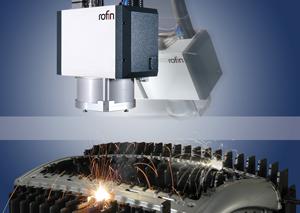
Remote laser welding uses scan mirrors for positioning the beam precisely at the desired weld location. A key requirement is a high-quality beam, so for many years, this limited remote welding to high-power CO2 lasers. A typical beam delivery system for such a setup consists of reflective optical components to direct the beam to the scan head for rapid deflection by the moving mirrors. The beam delivery system is somewhat fixed and requires the scan head to remain stationary, limiting the working volume.
With remote CO2 laser welding applications, system designers also faced other challenges, such as developing tooling to hold the workpiece in place, as well as delivering shielding gas to the weld zone. As the quality of disk and fiber-optic lasers has improved, delivering the beam via a transport fiber makes many of these obstacles shrink or disappear, clearing the way for innovative scanner system designs that are small and lightweight for agile positioning around the workpiece. Recent developments enable the simultaneous, coordinated motion of the scan mirrors and a robot for efficient weld processing on-the-fly.
System Requirements
The typical requirements for remote welding can be divided into three categories: the process parameters necessary to make the weld; the scanner features that deliver the beam adequately; and the laser beam quality sufficient for the long focal length of the system.
In general, to achieve an acceptable weld, a multikilowatt laser must be focused to a spot diameter of approximately 0.6 mm at the image plane. The optimum working distance (approximate distance from beam entry into the scan head to the workpiece) of 500 mm is advantageous because it allows sufficient room for tooling and scan-head positioning for the various weld locations while minimizing the opportunity for contamination.
Perhaps the most important parameter for remote laser welding is the beam quality of the laser. To achieve a focus spot diameter of 0.6 mm with a long working distance, the beam parameter product (BPP) must be less than 18 mm-mrad entering the scan head (see Figure 1).
Early Applications
During the mid-1990s, manufacturers of plastic components such as under-hood containers and key fobs began to employ scanned beam positioning techniques to join one part (somewhat transmissive) to the other (absorptive) to produce a complete assembly. The scan head was used to scan the beam rapidly along the desired weld path. Similarly, faced with the need to increase throughput, disk drive component manufacturers replaced fixed laser beam weld stations with scanners to spot-weld suspension arm components rapidly. Although low in power, these applications introduced a new concept: moving, low-mass mirrors with high accelerations and high speeds to reduce unproductive time for part positioning and increase the laser beam on-time.
Higher-power CO2 applications began to emerge at the new millennium. Initially, 1-kW to 2-kW CO2 lasers were used with scanners to weld small structures. One typical application is automotive heat exchangers. These consist of thin metal sheets that are difficult to join with conventional spot welding. Remote laser welding, a noncontact process, is an ideal process for quickly making the several welds each heat exchanger needs without distorting the material. The scanner covers a working area approximately 500 mm by 500 mm, producing a spot approximately 0.45 mm with a 2-kW CO2 laser. A scanner for this application comprises a 3-D scan system with a 33- to 40-mm effective aperture, with two galvanometer-driven mirrors for the X and Y position and a dynamic Z axis to maintain the focus spot diameter throughout the working field.
Once the baseline is established, it is possible to apply these parameters to other applications that are similar in principle, but require modifications to achieve specific performance. For instance, welding larger, thicker parts requires more laser power to achieve essentially the same parameters as the baseline process. However, it is not simply a matter of scaling the scanner design; increasing the part size and laser power requires a more complex scanner system.
A scanner system capable of deflecting CO2 lasers up to 6 kW over a 1-m process area requires very large scan mirrors with apertures of 70 to 80 mm to achieve a focus spot diameter of 600 micron that is necessary to join the metal. Driving these large mirrors at high speeds puts severe stress on the servo amplifiers. For stable operation, the electronic boards are mounted to a water-cooled backplane. In addition, the beam delivery optics and entrance aperture of the scan head are water-cooled and the dynamic scan mirrors are air-cooled to prevent damage from the heat generated.
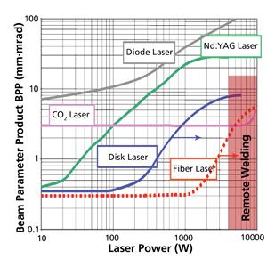
Figure 1 Regardless of the laser type, remote welding setups require 6 kW to 10 kW.
Scanner systems such as this have been employed worldwide to spot-weld automotive structural support panels in production environments. Remote welding with CO2 lasers grew quickly with numerous successful installations worldwide in just a few years.
Other Lasers Enter the Scene
Nd:YAG Laser. Short-wavelength lasers such as the neodymium-doped yttrium aluminum garnet (Nd:YAG) offered an alternative method of beam delivery. The laser beam can be piped into a transport fiber to guide it to the final delivery optics. Although convenient, the BPP of a fiber-delivered, diode-pumped, solid-state (DPSS) Nd:YAG laser is just barely good enough for the longer focal length systems typically associated with remote scanner welding. Although an Nd:YAG laser has a shorter wavelength than a CO2 laser, a scanner system for a DPSS Nd:YAG laser requires a large aperture (90 mm) to achieve the focus diameter sufficient for remote laser welding.
A system of this type is large, but still can be robotically positioned, offering simultaneous motion of the scanner and robotic positioner. This type of scanner is a 3-D system capable of achieving a working volume of 180 mm by 180 mm by 50 mm. With a 4-kW DPSS laser that has a beam quality of 18-mm mrad, a focus spot diameter of 0.7 mm is scanned within the working volume anywhere in the part that is within reach of the robot. A system of this type was installed to weld automotive structural components such as hoods and floor pans.
Fiber-optic Laser. Even early in its introduction, the fiber-optic laser (1,070 to1,090 nanometers) proved to be an improvement over existing laser technology for remote laser welding. The better beam quality from the 5-kW fiber-optic laser enabled further scanner aperture reduction to approximately 50 mm, yet still yielded a focused spot diameter at the image plane of 0.65 mm within a working volume of 200 mm by 200 mm by 100 mm. With the reduction in the size of the scan head, the robotic positioning system can deliver better performance, further reducing weld processing complexity.
Moving Forward, Robotically
Higher beam quality from the laser translates into design flexibility, which yields enhanced performance of all optical components for remote welding scanners.
The current state of scan-head technology for remote laser welding is a 3-D system with an input aperture of about 30 mm. This compact system can deliver up to 6 kW of power with a focused spot diameter of 0.6 mm within a volume of 240 mm by 200 mm by 80 mm.
Typically, this type of system has several sensors that monitor the scan-head operating conditions. Axis-monitoring sensors provide status of the X, Y, and Z axis values; power supply voltages; and electronic board status. System sensors monitor the temperature of the objective and protective windows, scan mirrors, collimator, and coolant flow. Internal beam splitters provide an interface for weld process monitors and vision systems. Digital servo controls allow selectable multiple tunings and communication channels for real-time feedback of the galvanometer's operating status.
Today's 3-D systems, which are more compact than ever, allow system designers to combine a remote welding scanner system with a robot to create a versatile workcell. Synchronizing the simultaneous motion of a scan head and robot gives system designers and process engineers ever-greater versatility and the ability to weld in unlimited orientations.
About the Author
About the Publication
subscribe now

The Fabricator is North America's leading magazine for the metal forming and fabricating industry. The magazine delivers the news, technical articles, and case histories that enable fabricators to do their jobs more efficiently. The Fabricator has served the industry since 1970.
start your free subscription- Stay connected from anywhere

Easily access valuable industry resources now with full access to the digital edition of The Fabricator.

Easily access valuable industry resources now with full access to the digital edition of The Welder.

Easily access valuable industry resources now with full access to the digital edition of The Tube and Pipe Journal.

Easily access valuable industry resources now with full access to the digital edition of The Fabricator en Español.
- Podcasting

In this episode of The Fabricator Podcast, Caleb Chamberlain, co-founder and CEO of OSH Cut, discusses his company’s...
- Trending Articles
1
AI, machine learning, and the future of metal fabrication

2
Employee ownership: The best way to ensure engagement

3
Steel industry reacts to Nucor’s new weekly published HRC price

4
Dynamic Metal blossoms with each passing year

5
Metal fabrication management: A guide for new supervisors
