


Design objectives for robotic welding fixtures
Robotic welding efficiency
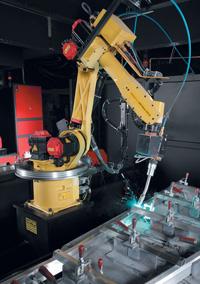 |
Robotic welding can improve your productivity, but its efficiency depends greatly on fixturing design and functionality.
When applied properly, robotic welding can be economical; on the flip side, it can be inefficient and cost-prohibitive if you overlook simple fixture design considerations first. You can realize—or lose—many productivity gains at the design stage.
When you're beginning a new robotic arc welding project, consider the following fixture design components:
- Material
- Welding circuit optimization
- Orientation and deposition rates
- Accessibility, repeatability, simplicity, and dependability
- Alternatives when fixture design costs are prohibitive
Choosing Robotic Welding Fixture Material
For the purposes of this article, fixturing refers to a custom-designed device used to locate or support the workpiece during welding. Although the words fixturing and tooling often are used interchangeably, tooling usually is defined as a specific device designed to form, compress, or shape.
One of the first steps in designing a robotic welding fixture is choosing its base metal. Factors include initial cost; long-term maintenance costs; and special characteristics that make it suited to a robotic welding application, such as maintaining accuracy and part repeatability in an environment exposed to elevated heat and weld spatter.
Common material options are mild steel, high-carbon tool steel, aluminum, stainless steel, and copper. Various alloys are available to improve work hardening and wear resistance. Each material has different characteristics that can affect productivity and quality (see Figure 1).
From an initial cost standpoint, square or rectangular structural steel tubing is economical for a majority of the fixture's framework. From a wear resistance standpoint, fixture hard stops and locating points often are made of alloyed high-carbon tool steel to help resist deformation. Another commonly sourced wear-resistant alloy, aluminum-bronze, work-hardens and isn't as prone as tool steel to residual magnetism.
 |
| Figure 1 Choosing a fixture base metal is a critical step in designing your fixturing. Several material characteristics play significant roles in the success of the fixture's design and function. |
Pure copper generally is avoided when hardness is a consideration; however, it's typically the best all-around material for electrical conductivity. Electrical conductivity is critical for arc welding stability, a desirable and necessary aspect for achieving maximum travel speeds. Because pure copper is such a good electrical conductor, alloys of copper and zinc (brass) or copper and tungsten carbide can be used to help improve copper's wear resistance.
Also note that novice fixture- builders sometimes overlook electrical conductivity and paint all surfaces, including the bolted work cable connection surface; this can cause immediate start-up problems.
Aluminum and copper both have high thermal conductivity—the ability to conduct heat—so they often are used for heat sinks that conduct heat away from the workpiece and spread the heat over a larger surface area. This helps minimize workpiece distortion.
 |
| Figure 2 When setting up fixturing, make sure to avoid combining all of the work leads into one lead to reduce the arc interference and induced magnetism, otherwise known as arc blow. |
In addition to thermal conductivity, you also should consider thermal expansion properties when selecting fixture material. Thermal expansion is the fractional change in the length of a material for a unit of change in temperature. Aluminum, for example, can change in length and volume significantly when it's heated. Because of this, copper is used more commonly for heat sinks, and aluminum typically is avoided to help the system achieve good part repeatability. Workpiece subassemblies also can be arranged and programmed physically with advanced welding processes and designed for low heat input to minimize welding distortion tendencies.
Optimizing the Welding Circuit
Refined welding waveforms require an optimized welding circuit to maintain short arc lengths while reducing spatter, stubbing, arc flare, and arc outages to maximize travel speeds.
Take special care to identify the optimum location of the work lead on the robotic welding fixture. Generally, the work cable and sense lead (if applicable) should be as close to the welding arc as possible, rather than placed indirectly through a series of bolted connections. Connecting directly to the workpiece is preferred.
Make sure that the work cable and sense lead are separated from each other, and from any robotic or welding communication cables, to help ensure the best results. When more than one power source is welding simultaneously on a single part, each power source requires a work lead from the work stud to the workpiece (see Figure 2).
 |
| Figure 3 Connect all welding work leads at the beginning of the joint and all work sense leads at the end of the joint. Be sure to connect all of the work sense leads from each power source to the workpiece at the opposite end. |
At this point also consider the anticipated welding travel direction. Preferably, welding should move away from the work lead (seeFigure 3). Connect all of the work sense leads from each power source to the workpiece at the opposite end.
Maximizing Robotic Welding Fixture Deposition Rates
Next, examine how your fixtures position the work relative to a vertical orientation so it takes advantage of the force of gravity (see Figure 4). When welding a part in the flat position, gravity is an ally. The finished welds are flat, uniform, and more easily made with higher deposition rates; this increases travel speeds and productivity directly.
 |
| Figure 4 The way you position your fixtures directly affects your travel speeds and productivity. Position fixtures to the work so they take advantage of gravitational forces, which will help produce welds that are flat, uniform, and more easily made with higher deposition rates. |
When sheet metal applications are designed with lap or T joints, positioning the part to allow a 15-degree downhill torch motion can increase travel speed 10 percent to 25 percent. Such positioning uses gravity, as well as the fast-follow characteristics of many consumable-gas combinations, to its advantage.
Note that although you may find welding overhead appealing for reducing or eliminating weld spatter from sticking to the part, the spatter inevitably will stick to the exposed surface of the fixture and tooling, requiring long-term maintenance. Welding overhead also requires you to overcome gravity. Deposition rates also are lower, and it's more difficult to maintain proper weld contours.
Options for Robotic Welding Fixture Design
You can choose from several clamping and locating options when you design a fixture.
Manual and Modular Fixtures. In the least complex fixture, simple manual clamping is applied to a fixed or stationary table. In an R&D or short-run setting, these are simple, low-cost methods to locate a part. Although manual fixturing can be labor-intensive, it's also flexible and versatile in these settings. Modular fixturing is another option that provides benefits of flexibility while maintaining dimensional control.
Dedicated Fixtures. On the other end of the spectrum, more complex applications may require a dedicated fixture. These more complicated fixture installations come with higher initial costs and frequently involve installing and routing wiring and pneumatic or hydraulic lines. Automatic clamping can reduce or eliminate labor involvement for actuation, part proximity sensing, and sequenced clamping.
Retrofitted Semiautomatic Fixtures. Another fixture design alternative involves retrofitting an existing semiautomatic fixture, but this alternative requires caution. In a semiautomatic application, the operator often makes on-the-fly adjustments to accommodate variation in joint location and geometry. When a robot is applied to the same fixture, any part movement dooms the assembly to the reject bin. If the fixture is dedicated predominantly to fillet and lap welds, the fixture typically can be reused, but outside corner welds and square butt joints often require serious enhancements to the existing fixture to maintain repeatability.
Each of these options requires you to consider a variety of objectives. For example, the fixture should be designed both to operate at an ergonomic height and reach and without needing operator force during loading and unloading. You also should emphasize sufficient torch accessibility and visual clearance, supplemented by adequate lighting.
Fixture surfaces ideally are designed to minimize flat surfaces; this helps prevent collected weld spatter from interfering with critical locating surfaces or actuating components.
When you're integrating a fixturing and clamping or locating device, make sure that the weld joint location repeats, in a 3-D space relative to the system, within plus or minus half the diameter of the welding wire being used. For example, a 0.045-inch-diameter wire allows a tolerance of ± 0.022 in.
Also ensure that gap location and width are consistent from part to part, with the same tolerances as the weld joint location. If your weld joint location isn't plus or minus half the diameter of the wire thickness, the weld size may need to increase to offset the resulting smaller weld. A larger weld may require 125 percent to 200 percent more weld metal than required if proper fit-up isn't maintained.
Good fit-up is critical to controlling costs. To obtain good fit-up consistently, you should concentrate on preconditioning operations such as cutting and shearing, machining, heat treating, and bending and forming.
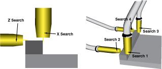 |
| Figure 5 Touch sensing requires a robot to touch the welding wire to the part in several places to determine part location and orientation. |
Alternatives to Cost-prohibitive Fixture Designs
Sometimes it's too expensive to manufacture parts to tight tolerances or impractical to present a large fabrication to a robot fixture within thousandths of an inch. Small part runs also may prohibit you from applying some fixturing options. In these cases, software sensory technology such as touch sensing or through-the-arc seam tracking can help overcome part or fixture deficiencies.
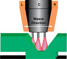 |
| Figure 6 In through-the-arc seam tracking, a robot can change its path if necessary if it senses a joint location shift. |
With touch sensing (seeFigure 5), the robot is programmed to touch the welding wire to several locations on the fabrication to identify the part location and orientation. A master program can use this information to shift three-dimensionally to match up with the new part orientation.
Through-the-arc seam tracking (see Figure 6) also can be enabled once the robot begins welding. In this case, the robot weaves across the weld joint and modifies its path based on any joint location shift caused by distortion or part springback, for example.
Other, more complex sensing and tracking methods include laser-based vision systems.
When properly applied, robotic welding can be economical. But fixturing is paramount—if you overlook simple fixture design considerations, robotic welding can be inefficient and cost-prohibitive. The fixture design stage is a critical time for you to realize—or lose—productivity gains. Considering basic fixture design objectives will help you make the most of your robotic welding system.
Geoff Lipnevicius is engineering manager, automation division, The Lincoln Electric Co., 22801 St. Clair Ave., Cleveland, OH 44117, 216-481-8100, fax 216-486-1751, www.lincolnelectric.com.
About the Author
About the Publication
subscribe now

The Fabricator is North America's leading magazine for the metal forming and fabricating industry. The magazine delivers the news, technical articles, and case histories that enable fabricators to do their jobs more efficiently. The Fabricator has served the industry since 1970.
start your free subscription- Stay connected from anywhere

Easily access valuable industry resources now with full access to the digital edition of The Fabricator.

Easily access valuable industry resources now with full access to the digital edition of The Welder.

Easily access valuable industry resources now with full access to the digital edition of The Tube and Pipe Journal.

Easily access valuable industry resources now with full access to the digital edition of The Fabricator en Español.
- Podcasting

In this podcast episode, Brian Steel, CEO of Cadrex Manufacturing, discusses the challenges of acquiring, merging, and integrating...


