


Director of Engineering
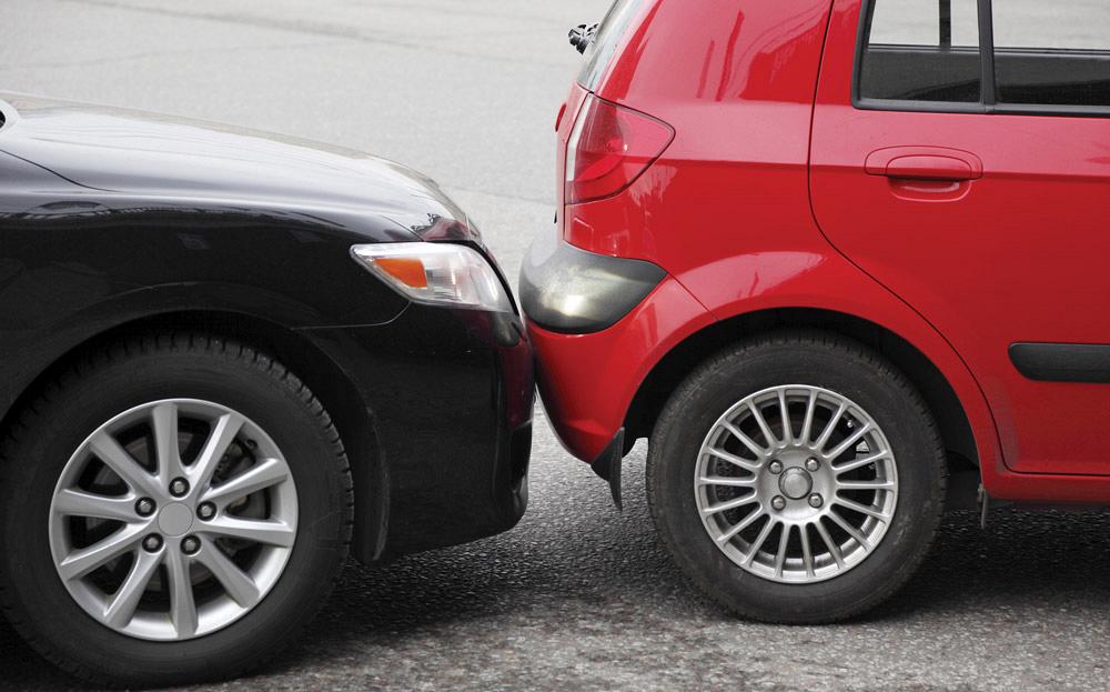
Bumper systems are the first line of defense in a collision and are designed to absorb impact, so they must be strong. But they must also be part of automakers’ lightweighting efforts to achieve fuel efficiency. Optimized geometries can help achieve this balance.
(Editor’s Note: This article has been adapted from the Great Designs in Steel 2015 conference presentation entitled “Localized Buckling Solutions for Thin-gauge UHSS Bumper Beams.”)
The use of advanced high-strength steels (AHSS) and even ultrahigh-strength steels (UHSS) is growing rapidly in the automotive industry. The advantage of high-strength steels is that they can absorb energy at thinner gauges than mild steels, so metal formers can reduce mass by up to 20 percent by using them.
The high strength and high ductility characteristics of UHSS come from the metal’s unique microstructure. Elongation, the property that imparts formability, generally decreases as strength increases. However, some grades of UHSS with strengths up to 1,500 megapascals (MPa) have been formulated to also retain the formability associated with low-strength steels.
Bumper systems are important in the energy management of vehicles at low-speed impact and also for pedestrian safety. Using UHSS to downgauge bumper systems reduces mass. Research studies show that approximate savings of 15 to 25 percent of mass are possible by using UHSS to form bumpers.
As bumper gauges progressively get thinner, localized buckling occurs. Localized buckling is a phenomenon in which the tubular column buckles or collapses its section before it reaches the yield. This has become a forming challenge.
Geometry plays a major role in addressing the localized buckling problem. An integrated optimization methodology has been proposed to study this particular problem. In this methodology, a design of experiments (DOE)-based optimization method is applied that exerts a combination of changes to the bumper within parameters of the three G’s—gauge, grade, and geometry. Based on the experiment’s results, it is possible to construct a response surface method and discover the best design to form a light yet stable bumper.
The Insurance Institute for Highway Safety’s (IIHS) low-speed crash test finite element analysis (FEA) modeling and the three-point bending tests were used for this study.
Three-point Bending. First, the three-point bending test was performed on various material grades of UHSS—DP1180, MS1300, and MS1500, with DP780 at 1.2 millimeters thick as the baseline material—to identify the mass savings that can be achieved on each, theoretically. Researchers progressively reduced the material gauges of each grade until they arrived at a minimal thickness with an equivalent baseline performance. That way they could ascertain how thin each UHSS material could get without compromising the bumper’s strength.
Their tests indicated that material grades DP1180, MS1300, and MS1500 could be reduced to 0.95, 0.90, and 0.90 mm, respectively, with mass savings of 0.68 kg, 0.82 kg, and 0.82 kg (see Figure 1). Once researchers completed that test, they could introduce geometry variables.
Geometry Optimization. Next, researchers used the IIHS low-speed crash test FEA model for the optimization study. All three sets of variables (gauge, grade, and geometry) were tested on the grades and gauges selected in the first part of the study—0.95-mm DP1180, 0.90-mm MS1300, and 0.90-mm MS1500.
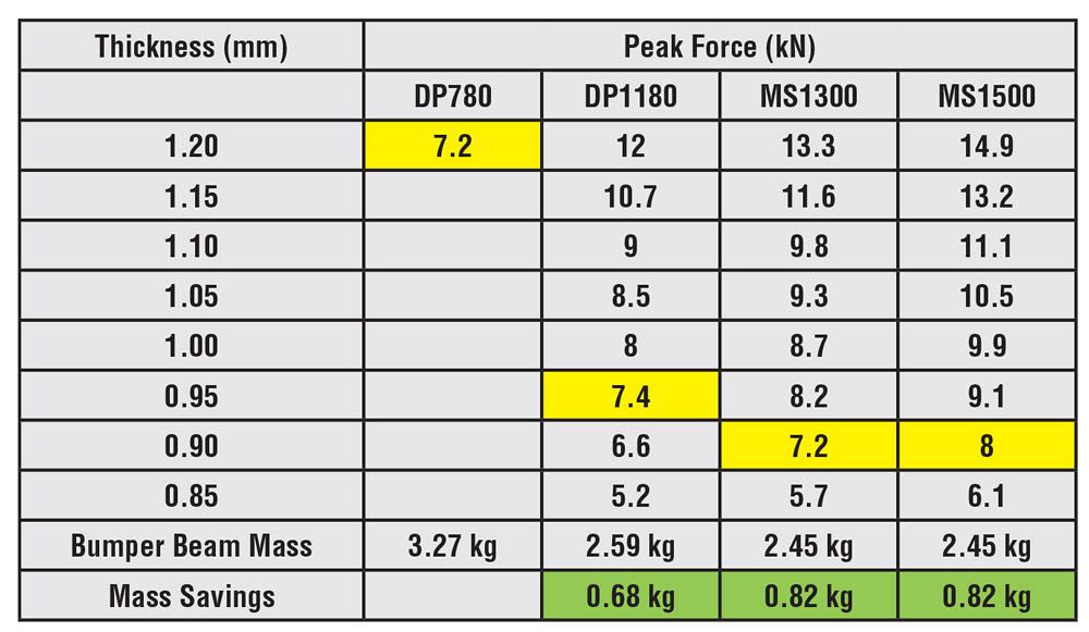
Figure 1
Tests indicated that material grades DP1180, MS1300, and MS1500 could be reduced to
0.95, 0.90, and 0.90 mm, respectively, with mass savings of 0.68 kg, 0.82 kg, and 0.82 kg.
Variable geometry changes were implemented using morphing technology. In recent product development, morphing technology has been used widely to reduce the design cycle time. It is standard in most computer-aided engineering (CAE) preprocessors.
The researchers selected the MeshWorks™ platform for this optimization study because they could readily apply all the geometry changes on the base models and generate different designs with different shape changes. The program parameterizes the base models for all three variables—gauge, grade, and geometry.
Bumper geometry variables are very impactful and are significant in resolving the buckling problems that occur during mass optimization. Some of the most important shape parameters are:
An optimized bumper beam shape can be achieved by varying these geometry characteristics. Which of the variables is most suitable depends on which manufacturing process and design space constraints are chosen. Once the parameters and their ranges have been identified, the base model will be parameterized with all the variables, and multiple DOE models can be generated.
These models will be solved for IIHS’s low-speed test condition and the DOE results tabulated for the list of the outputs (see Figure 2). The outputs can be the bumper section force, local buckling distance, and intrusion. The results table (input and output for all DOE runs) can be used to construct a response surface model and solve the optimization problem. Normally, optimization minimizes mass while retaining strength and without buckling.
All of the material thickness and shape optimization techniques must be considered within the realm of the manufacturing process used to form it. Case studies were conducted to determine the optimal configuration for each process and material gauge.
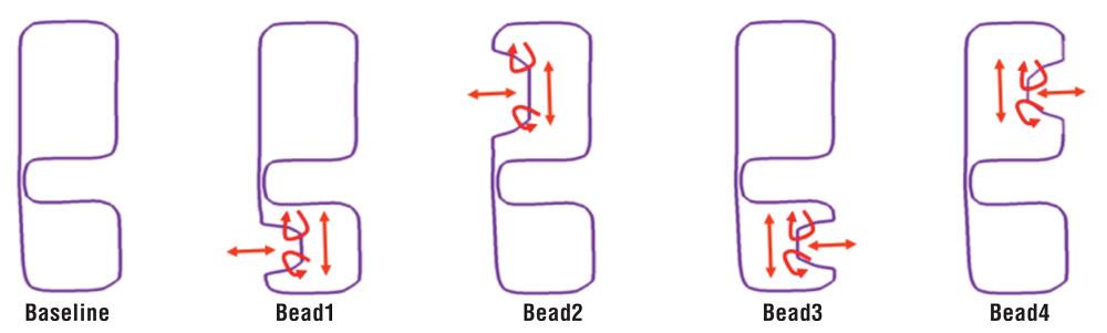
Rolled Formed Bumper. Along with material and gauges—0.95-mm DP1180, 0.90-mm MS1300, and 0.90-mm MS1500—shape variables such as bead and hinge parameters were considered for the study (see Figure 3).
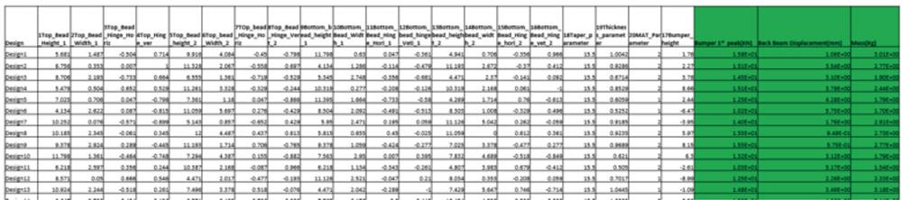
The DOE-based optimization calculated a total of 25 design variables including gauge, grade, and geometry (see Figure 4).
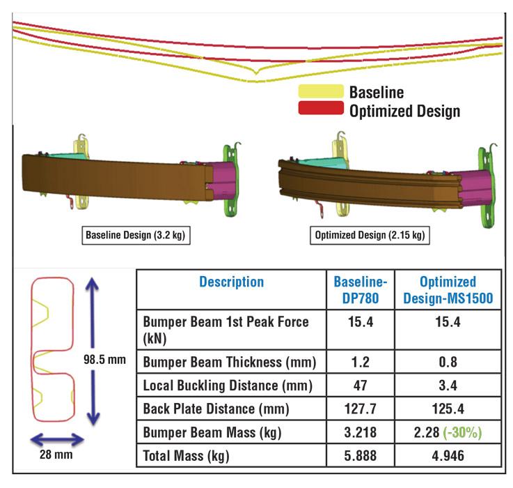
The optimized design of MS1500 is about 30 percent lighter than the baseline material and is a much more stable section, as tested at IIHS low-speed impact, with no local buckling or compromising of performance (see Figure 5). Front face beads are an important factor in stabilizing the bumper beam. The gauge can be as thin as 0.8 mm and still be effective.
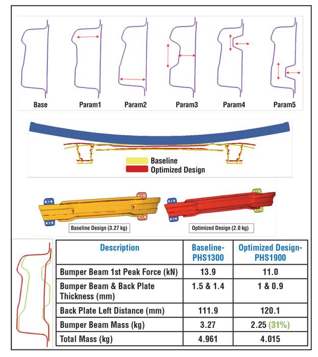
Hot-stamped Bumper. The baseline hot-stamped bumper design was around 3.27 kg and stamped from PHS1300 material. The material tested for the optimized application was PHS1900. Multiple shape parameters were created on both bumpers and the back plate. Each bead corner varied in its depth parameter, height parameter, and hinge parameter.
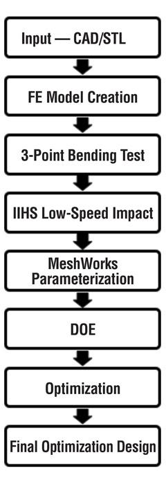
Figure 2
This model shows all the steps in sequence
to optimizing a process.
Optimization was completed with a total of 52 design variables and 277 DOE runs (see Figure 6).
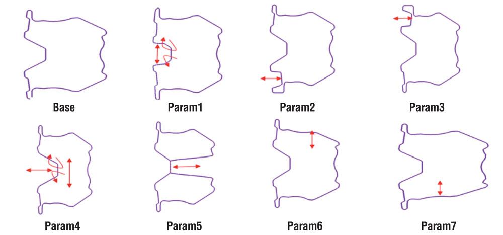
Hot-rolled Bumper. Again, the baseline bumper was made of PHS1300. The UHSS material chosen for the test was PHS1900.
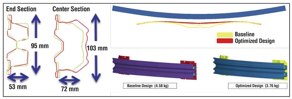
A hot-rolled bumper has a very complex shape and the section is not uniform across the length of the bumper. Researchers defined a total of 14 shape and gauge parameters using MeshWorks (see Figure 7). The final optimized design was compared against the baseline (see Figure 8).
Research shows that forming bumper systems from UHSS and optimizing their geometries can lighten them. Morphing and parameterization processes help to reduce product design cycle time substantially. This approach can be used universally in all applications to optimize processes.
Design of Experiments. DOE is a Six Sigma-originated systematic method of determining the relationship between factors affecting a process and the output of that process. It is used to find cause-and-effect relationships for the purposes of managing process inputs to optimize the output.


The Fabricator is North America's leading magazine for the metal forming and fabricating industry. The magazine delivers the news, technical articles, and case histories that enable fabricators to do their jobs more efficiently. The Fabricator has served the industry since 1970.
start your free subscription
Easily access valuable industry resources now with full access to the digital edition of The Fabricator.

Easily access valuable industry resources now with full access to the digital edition of The Welder.

Easily access valuable industry resources now with full access to the digital edition of The Tube and Pipe Journal.

Easily access valuable industry resources now with full access to the digital edition of The Fabricator en Español.
In this episode of The Fabricator Podcast, Caleb Chamberlain, co-founder and CEO of OSH Cut, discusses his company’s...


