


Contributing Writer
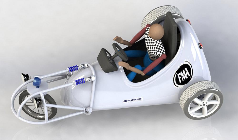
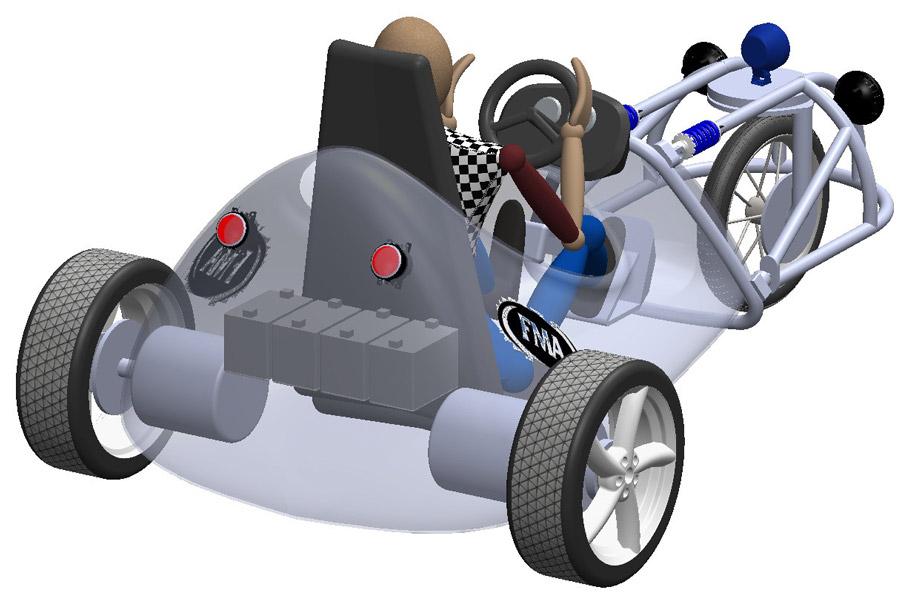
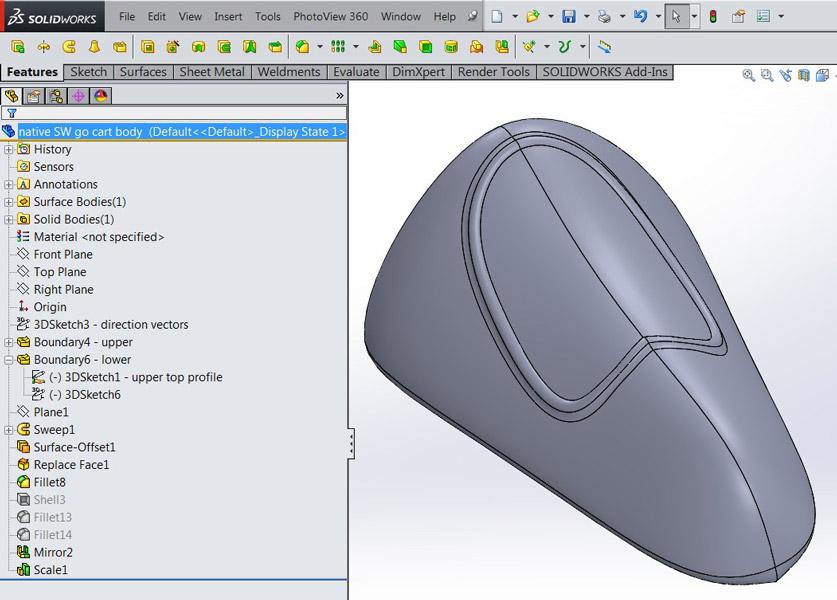
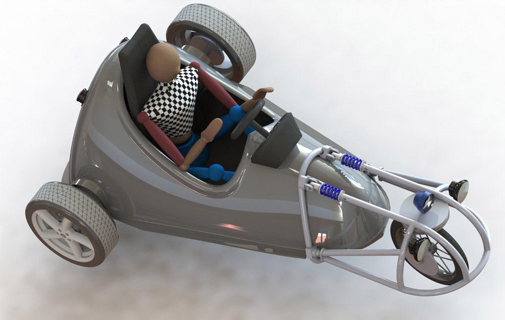
Figure 1a
This virtual prototype of an electric go-cart has a body
shell that connects to a front wheel assembly. The upper
body features a seat and rear axle cutouts.
Editor's Note: If you would like to download the 3-D CAD files associated with this column, click here.
The electric go-cart shown in Figures 1a, 1b, and 1c is an imaginary prototype used to pose a challenge: Our modeling scenario requires that we fabricate the body in CAD.
As background, the pair of motors steer this tricycle. The front wheel is just a caster. By turning one motor faster than the other, the driver is able to change the vehicle direction. This gizmo might be better suited for an amusement park than the open highway.
We’ve joined the design team fairly early in the project. In Figure 1a we note that the front wheel assembly is bolted somehow to the body shell. Figure 1b implies that the body shell is a structural element. Figure 1c emphasizes that the design is incomplete—the drive motors float in location by magic, batteries are not mounted, and brake calipers and wire looms have yet to be created.
Not to be deterred as fabricators, we have a basic shape to work with.
Our form is defined by a target design, also known here as the prototype. Our goal is to create 3-D models that resemble fabricated parts. We want these models to reflect practical considerations that arise from materials and processing.
The plan is to use the original as a tool to essentially vacuum form the part in sheet stock. We actually need a pair of forming tools, one for the upper body and one for the lower body.
In the realm of function, we need some way to assemble the cart. Breaking the body into two pieces makes that easier. We’ll add a clamping flange, and we’ll also make room for the motors to connect to the wheels.
We begin a fabricating model based on the prototype. Figure 2a is our first departure from the original prototype. We are basically saving a copy of the original model and using that copy to create tooling. We will create the copy by exporting the master model to an interchange format, IGES in this example, and then importing that IGES file as a starting point for our tooling.
The advantage of the dumb model over the native CAD is primarily with areas of responsibility. We have no need to edit the original design intent or form. The dumb model is safe and is also faster to rebuild for the computer hardware.
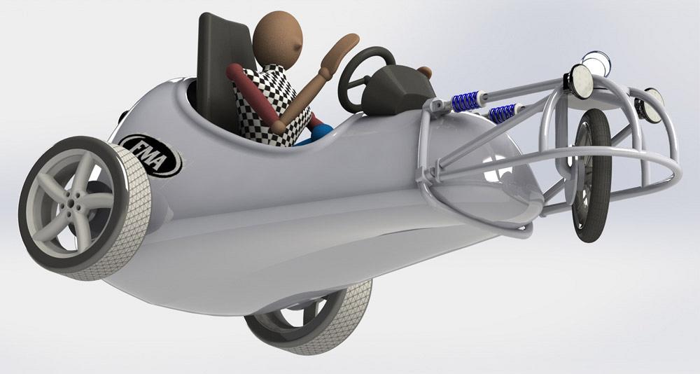
Figure 1b
This image shows the floor of the body. There is an odd
seam in the floor that would be difficult to fabricate.
Because we have access to the original CAD, we took the time to fill in the open holes before exporting the model (see Figure 2b). Those holes could have been filled in after importing, but the key is to grab the low-hanging fruit where you can. (That’s a CAD tip for those scoring at home.)
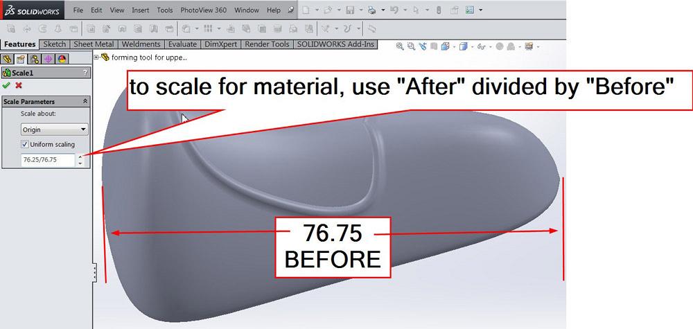
It doesn’t really matter which CAD software was used to create the original prototype. We now have the 3-D model imported into our CAD system (see Figure 2c). Our first action is to scale the model to compensate for the material thickness. In this example, the original IGES was 76.75 in. long. Our target material thickness is 0.25 in., so we need to reduce the overall length by 0.5 in. In Figure 2c, the scaling factor was set as 76.25/76.75, which is “after” divided by “before.”
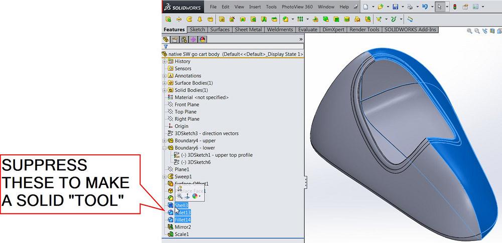
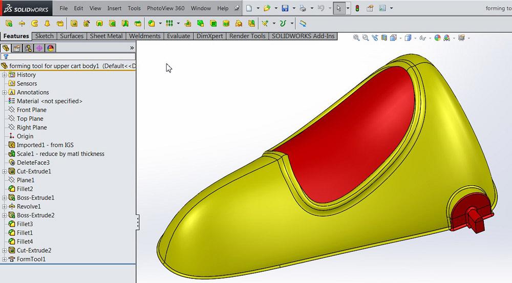
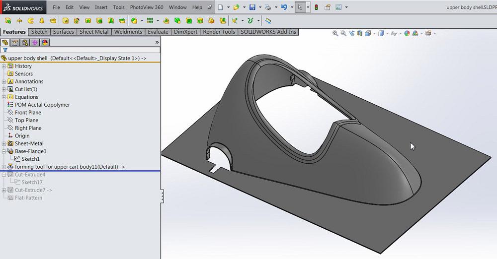
In Figure 2d the remainder of the edits have been completed to create the upper forming tool. To summarize the changes made to the original:
Not shown in Figure 2d but also required is the fact that this forming tool model was saved in a library folder that was declared to be a Forming Tool folder. That’s pretty specific to a brand of CAD. The result is drag and drop of the forming tool on a model of sheet metal.
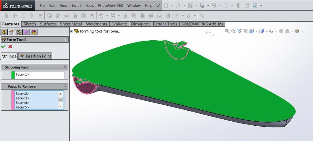
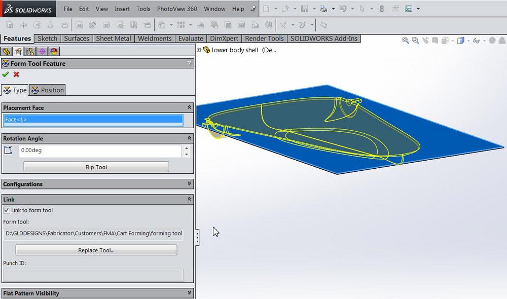
In Figure 2e we see the lower forming tool. As mentioned before, it was created as a copy of the upper forming tool. Then the direction of cut and a few other little changes resulted in a forming tool very similar to the upper forming tool. In Figure 2e we see the properties that define a forming tool. The Stopping Face is selected in green, and the Faces to Remove is shown in red.
The software tools we’re using are for sheet metal, but in this example, our sheet stock is 0.25-in. KYDEX® plastic. The upper forming tool has been applied to the sheet stock in Figure 3a. Note that faces have been removed by the forming tool. In Figure 3b we see the process of applying the lower forming tool to another bit of raw stock.
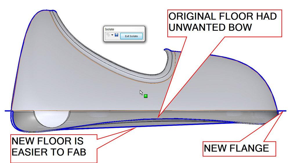
After creating the fabricated models, we need to verify that the new parts work as well as the original prototype. Figure 4 shows a cross section of an assembly with both the new lower shell and the original prototype. The original model had a bow in the floor that would require secondary pressure to form. Our edits to the model included flattening the floor for easier stretching of material.
Figure 5 shows the test-fit of the upper and lower shells with the frame. An assembly cut was used to propagate a trim cut to clear the front caster. We’ll submit this design to the team for their consideration. If this idea of upper and lower shells works, we’ll probably work on taillights. Those lamp bezels could be modeled with forming tools too.
It may turn out that fiberglass or some other composite would be better than soft thermoformed plastic for this application. As a CAD modeling technique, forming tools can be very efficient, regardless of the real-world material.
Gerald would love to have you send him your comments and questions. You are not alone, and the problems you face often are shared by others. Share the grief, and perhaps we will all share in the joy of finding answers. Please send your questions and comments to dand@thefabricator.com.


The Fabricator is North America's leading magazine for the metal forming and fabricating industry. The magazine delivers the news, technical articles, and case histories that enable fabricators to do their jobs more efficiently. The Fabricator has served the industry since 1970.
start your free subscription
Easily access valuable industry resources now with full access to the digital edition of The Fabricator.

Easily access valuable industry resources now with full access to the digital edition of The Welder.

Easily access valuable industry resources now with full access to the digital edition of The Tube and Pipe Journal.

Easily access valuable industry resources now with full access to the digital edition of The Fabricator en Español.
In this episode of The Fabricator Podcast, Caleb Chamberlain, co-founder and CEO of OSH Cut, discusses his company’s...


