


Professor Emeritus and Director - Center for Precision Forming

Editor's Note: This article discusses the recent advances made in the simulation of the hot-stamping process. A three-part article providing an overview of this growing technology appeared in the December 2006, January 2007, and February 2007 issues of STAMPING Journal®.
The use of ultrahigh-strength steel (UHSS) in the automotive industry has increased in the last few years as manufacturers try to improve crash safety and reduce weight. Parts such as B-pillars, side impact reinforcement beams, and bumpers are increasingly manufactured from UHSS by hot stamping.1
In hot stamping, the blank is heated in a furnace to its austenitization temperature (about 900 degrees C), formed in an internally cooled die set, and quenched under pressure at a minimum cooling rate of 27 degrees C per second. This minimum cooling rate ensures the formation of martensitic microstructure in the part, which gives it strength of about 1,500 MPa.
Finite element (FE) simulation of the hot-stamping process can help manufacturers predict such final part properties as thickness, temperature, and hardness distribution.
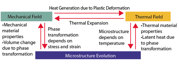
Mechanical deformation, heat transfer, and microstructure evolution occur simultaneously during hot stamping (see Figure 1). This makes FE simulation of the process challenging. Most researchers use a combination of different FE codes to capture what occurs during hot stamping.
When using FE simulation, making suitable assumptions while ignoring the effects of some of the less significant parameters can help shorten the time needed to obtain reasonably accurate results. Some parameters, however, are required as input to the FE codes.
The essential material properties include emissivity and flow stress as a function of temperature, strain, and strain rate. Also required are Young's modulus, Poisson's ratio, thermal conductivity, specific heat capacity, and coefficient of thermal expansion, each as a function of temperature.
The essential process parameters are final austenitization temperature; blank transfer time; blank temperature as forming begins; die stroke versus time; contact heat transfer coefficient between the blank and tool as a function of pressure and distance between the tool and die surface; coefficient of friction as a function of pressure; initial tool temperature for nonisothermal simulation; average tool temperature for isothermal simulation; temperature of the cooling medium needed to cool dies; blank holder force; closing pressure of the tools; and time required for quenching and air cooling.
In the hot-stamping process, forming and quenching simulation are most important, since most of the deformation and heat transfer take place during these two operations.
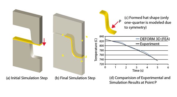
The Center for Precision Forming (CPF) is developing an FE-based procedure for the simulation of hot-stamping operations, applying the process to the design of various hot-stamping dies. For instance, CPF used DEFORM™-3D to simulate the forming of a simple hat shape from a 22MnB5 blank at an initial temperature of 827 degrees C.3 During the experiment, temperature was measured at Point P (see Figure 2) using a thermocouple. This thermocouple measurement was later compared with the simulation.
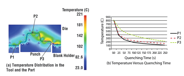
Determining the optimal size and location for cooling channels is very important in hot-stamping tool design. During the design of cooling channels for complex parts like a B-pillar, heat transfer simulations can be used on critical 2-D sections of the part to determine cooling channel size and location. Based on the results obtained from the 2-D simulations, the initial cooling channel configuration can be selected for the whole part.
Figure 3 shows the temperature distributions in the tool and part during quenching simulation for a selected section in a B-pillar after 10 hot stampings.
FE simulation of hot stamping poses many challenges:
CPF, other research groups, and software companies are addressing these issues to develop software design tools to improve die and process design.
Ambikapathy Naganathan and Deepak Ravindran are graduate research associates and Taylan Altan is professor and director of the Center for Precision Forming (CPF), The Ohio State University, 339 Baker Systems, 1971 Neil Ave., Columbus, OH 43210-1271, 614-292-9267, www.cpforming.org.

Professor Emeritus and Director - Center for Precision Forming


The Fabricator is North America's leading magazine for the metal forming and fabricating industry. The magazine delivers the news, technical articles, and case histories that enable fabricators to do their jobs more efficiently. The Fabricator has served the industry since 1970.
start your free subscription
Easily access valuable industry resources now with full access to the digital edition of The Fabricator.

Easily access valuable industry resources now with full access to the digital edition of The Welder.

Easily access valuable industry resources now with full access to the digital edition of The Tube and Pipe Journal.

Easily access valuable industry resources now with full access to the digital edition of The Fabricator en Español.
In this episode of The Fabricator Podcast, Caleb Chamberlain, co-founder and CEO of OSH Cut, discusses his company’s...


