


Using laser shock peening to increase pilger die life
Case-hardening for reducing tools
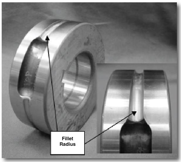
Figure 1. Two views of a standard pilger die show the entrance portion of the die, where the tubing first encounters the pilger process. The area of maximum stress varies by application and is influenced by tube material, input and output tube size, roll groove design, and roll die diameter.
Cold pilgering, or tube reducing, is a cyclic metal forming process performed at room temperature that reduces a metal tube's cross section by a combination of wall thinning and diameter reduction. Pilgering usually is used to change the characteristics of seamless tubing to make it suitable for high-fatigue-strength applications such as aircraft hydraulic lines. Other applications for pilgered tubes include commercial heat exchangers, zirconium nuclear fuel cladding, and aircraft engine components.
The cyclic process of rolling a set of pilger dies often leads to fatigue failure. A combination of variables defines the location of highest stress on the pilger tools. For pilger reduction applications in which the applied tooling stress is high enough, fatigue cracking in the base of the roll die groove is the typical mode of failure (see Figure 1 and Figure 2). Fatigue cracking also is influenced by the use of water-based flood coolants, and the expected failure mode is fatigue, stress corrosion cracking, or corrosion fatigue.
Shot peening is a commercial method that produces near-surface compressive residual stress. It increases the fatigue life of metal components by reducing the likelihood for fatigue crack initiation. Shot peening can generate a compressive residual stress to a depth of 0.004 to 0.008 inch, depending on the material and the peening conditions.
Another process, laser shock peening (LSP), can impart compressive stresses to depths that exceed 0.100 in. This isn't just a research or prototyping tool—this process is used in producing a variety of aircraft components.
LSP uses a series of high-intensity laser pulses to generate deep residual compressive stresses in a specified location. The process does not require component support, and it is suitable for use on many titanium-alloy and steel components.
LSP isn't intended to replace shot peening; rather, it is an additional process that can be used in specific areas where shot peening doesn't provide the necessary hardening. It's a complement, not a competitor.
Practical Peening Practices
The first step in LSP is to apply an overlay to the surface of the part. The overlay must be opaque to the laser beam. This opaque overlay, which can be black tape or paint, serves two purposes. It protects the part's surface from the plasma that is generated, which prevents melting the part's surface. It also provides a medium for the laser beam energy to couple with to produce a consistent residual stress profile for each laser pulse.
The second step is to establish a flow of water over the overlay, and the third step is to fire the laser. The beam passes through the water and strikes the opaque overlay, creating a plasma. The plasma is confined between the overlay and the water, which generates a shock wave, which penetrates the surface of the component. If the pressure in the shock wave exceeds the dynamic yield strength of the material, the stress wave cold-works the metal as it propagates through the metal.
The shock wave's pressure can be two times the dynamic yield strength of the material; the pressure gradually decreases as it propagates into the material, resulting in deep compressive residual stresses. They can be up to 10 times deeper than those generated by shot peening (see Figure 3 and Figure 4). They mitigate the tensile stresses, keeping a crack from initiating and propagating from the surface.`
The magnitude and depth of the compressive residual stresses can be tailored to meet specific needs of the component. Factors such as the laser beam's power density, pulse width, and spot spacing control the magnitude and depth of the residual stress profile. The deep compressive residual stress allows parts to be ground, polished, or "benched" after the application of LSP. This post-peening processing produces a unique combination of fine surface and residual stress not possible with shot peening.
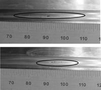
Figure 2. A visual inspection of the failure regions associated with a standard die (top) and an LSP-hardened die (bottom) reveals that the cracks are shorter in the LSP die after a similar number of cycles.
LSP: Where and Why
LSP is not meant to replace shot peening, but to supplement it. It typically is applied to such locations as fillet radii, where the curvature of the fillet combined with the loading stresses requires deeper treatment to retard the formation and propagation of a crack. This type of feature is encountered in the root radius of the pilger die groove, where the material to be pilgered comes into contact with the die.
The LSP process has improved the life of pilger dies where the groove used to form the tubing experiences high stresses, which are perpendicular to the longitudinal direction of the groove. The typical LSP location for a pilger die is the entrance area; this is the area of maximum tube reduction and maximum stress. Depending on the die, the application, and the LSP parameters, a treated die's service life can be six times that of an untreated die.
About the Author
About the Publication
subscribe now

The Tube and Pipe Journal became the first magazine dedicated to serving the metal tube and pipe industry in 1990. Today, it remains the only North American publication devoted to this industry, and it has become the most trusted source of information for tube and pipe professionals.
start your free subscription- Stay connected from anywhere

Easily access valuable industry resources now with full access to the digital edition of The Fabricator.

Easily access valuable industry resources now with full access to the digital edition of The Welder.

Easily access valuable industry resources now with full access to the digital edition of The Tube and Pipe Journal.

Easily access valuable industry resources now with full access to the digital edition of The Fabricator en Español.
- Podcasting

In this episode of The Fabricator Podcast, Caleb Chamberlain, co-founder and CEO of OSH Cut, discusses his company’s...
- Trending Articles
1
Team Industries names director of advanced technology and manufacturing

2
Orbital tube welding webinar to be held April 23

3
Chain hoist offers 60-ft. remote control range

4
Push-feeding saw station cuts nonferrous metals

5
Corrosion-inhibiting coating can be peeled off after use
