


Contributing Writer
 |
| Figure 1 |
Abrasive jet users need in-depth knowledge of nozzle mechanics, either for practical reasons, or simply to have the satisfaction of knowing what their machines really are doing. Two types of information fabricators need are generally known accepted physical laws, and empirical data resulting from testing that cannot be explained by physical laws.
First, let's look at a pure waterjet's formation and structure, beginning with the pump. Figure 1 shows the jet formation geometry. Upstream pressure accelerates the water through the water orifice, and abrasive then is mixed with the water and accelerated by it to form the cutting jet.
 |
| Figure 2 |
Water is a liquid usually regarded as being incompressible, and this is a sound statement at most ordinary pressures. However, at the high pressures used for driving an abrasive jet, water compresses up to 11 percent. Figure 2 shows the compression percentage at pressures up to 100,000 pounds per square inch (PSI).
For the mathematically inclined, the empirical equation from which Figure 2 is calculated is:
| ρ = ρ0(1 + P/53,000)0.162 | ||
| Where: | P = pressure in PSI ( 70 degrees F) | ρ = the fluid density |
Because of the compressibility factor, a pump plunger pumping at 50,000 PSI moves at least 10 percent of its stroke length before any water begins to exit the check valve. If the pump cylinder contains any dead volume, an even greater force is required.
At the end of the stroke, the dead volume is filled with energy containing compressed water. Pump mechanical efficiency depends on how well this stored energy is recovered.
The two main pump types on the market—crank drive and intensifier—differ in the ability to recover this energy. Crank drive pumps recover the expanding water's energy just like an engine recovers expanding hot gas energy. In the hydraulically driven plunger of an intensifier pump, the energy is dumped as heat into the hydraulic oil.
Compressibility is useful in smoothing out pulsation from the pumping equipment. Intensifier pumps typically pulse at about once per second with quite large pulses and use an accumulator comprising about 200 cubic inches of fixed water volume. The water's compressibility keeps the jet running during the intensifier's plunger reversal cycle.
Three-cylinder crank drive pumps always have at least some output and usually have enough compressed liquid in the normal plumbing to deliver a smooth output. The water compression also slightly affects the flow rate through the orifice that forms the jet.
Pressure pushes on the water and accelerates it through the orifice according to Newton's laws of motion. The pressure falls from the very high upstream pressure to atmospheric pressure, or even a bit below, as the water accelerates through the orifice. Whatever happens to the stream below the water orifice has no effect on the power required to drive the orifice, or the flow rate through it. Whether the stream is accelerating abrasives, cutting as a pure water stream, or simply squirting into the air, the flow and power are the same.
If water were not compressible, the relation between the speed of the water in the stream and the upstream pressure would be given exactly by the famous Bernoulli equation as:
| V = (2 x P/ρ)1/2 | |
| Where: | V = stream velocity | P = upstream pressure | ρ = the fluid density |
 |
| Figure 3 |
In actuality, because the water is compressible, the density continuously falls as the pressure drops and the water accelerates. By taking this effect into account, you can calculate the exact relationship between pressure and speed, which is shown as the bottom curve in Figure 3. Note that the speeds reach thousands of feet per second. In air, these speeds are supersonic and are faster than most high-speed rifle bullets. Also note that the exact compressibility results are very close to the more simple incompressibility approximation.
Water compression, while important for the pumping, is not very important for the flow through the nozzle. For this reason, most engineers use a more simple, incompressibility result presented later in this article.
It also is important to note that almost all water pressure changes occur across the water orifice. The mixing tube downstream of the orifice has a completely insignificant effect on the water flow through the nozzle. The cutting jet's flow rate and power consumption are determined entirely by the pressure and the water orifice size.
The preceding results fall in the scientific category—accepted physical laws—and as such are very accurate. The next step is to calculate the flow rate through the nozzle, which involves some empiricism.
Note that in Figure 1 the stream is smaller than the hole that formed it. How much smaller it is depends on the hole's edge. In general, as the radius on the edge increases, the stream becomes bigger relative to the hole, until, for a fully rounded inlet, it can fill the hole.
The orifice discharge coefficient (C d)is defined as the ratio of the stream area to the hole area. An orifice coefficient of 1.0 describes the condition in which the stream fills the hole. For most jet cutting applications, the coefficient ranges from 0.6 to 0.7. The uncertainty and variability in this value more than masks the compressibility effects mentioned previously.
Some literature refers to the orifice coefficient as an orifice efficiency, but this gives the false impression that it is in some way related to energy efficiency. In fact, the orifice almost perfectly converts pressure energy into the water's kinetic energy, with the orifice coefficient affecting only the amount of water flowing through its effect on the stream diameter.
The amount of water flowing, Q, simply is the stream area times the stream speed. Unfortunately, we usually know the hole size rather than the stream size, so the orifice coefficient is used to ratio the hole area down to the stream area. The equation for the flow through an orifice is:
| Q = Cd x ρ/4 x d2 x (2 x P/ρ)1/2 | |
| Where: | Q = flow rate | d = orifice diameter | Cd = orifice discharge coefficient |
| Q = 29.842 x Cd x d2 x (P)1/2 | This equation predicts the flow to within a few percent, with the major uncertainty coming from the orifice coefficient.|
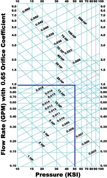 |
| Figure 4 Knowing two variables enables determination of two other variables. For example (note heavy lines), if a cutting pressure of 50 KSI is required using a 0.015 orfice, it will draw a flow of 1 GPM and the stream power will need a motor larger than 30 HP because of pump inefficiencies. |
As discussed, the power required to drive the jet is independent of what occurs with the jet in the mixing tube and below. The mixing tube and cutting process usually are treated as a single phenomenon to be investigated by experiment. This important second half of the flow process is described by empirical results rather than results from engineering calculations. In a publicly reported study by Zeng,1 results were gathered from a large series of experiments and equations were fitted to the data, resulting in the equation:
| V = | ( | fa x P1.594 x M x d1.374 x Ma0.343 ________________________________________ | ) | 1.15 | 163 x Q x H x Dm0.618 |
| Where: | V = traverse speed in IPM fa = abrasive factor (1.0 for garnet) P = stagnation pressure of waterjet in PSI, typically 50,000 PSI M = material machinability d = orifice diameter in inches, typically 0.014 in. Ma = abrasive flow rate in lb./min., typically 0.8 lb./min. Q = quality desired. Set to 1.0 for calculating separation speed H = material thickness in inches Dm = mixing tube dia. in inches, typically 0.030 to 0.040 in. |
| Machinability, M, of Various Materials | |
| Hardened Tool Steel Mild Steel Copper Titanium Aluminum | 80 87 110 115 213 |
Processes within the mixing tube are very complex. The flow contains high-speed water, abrasives, and air. By weight, the stream is approximately 90 percent water, 9 percent abrasive, and 1 percent air.
At the tube's top, the water is at the high speed calculated above. In fact, it is highly supersonic with respect to the air. The air and abrasives are moving very slowly in comparison. Within the 4-in.-long tube, violent action occurs when the abrasives are accelerated to about 1,000 ft./sec. This acceleration is about 46,000 times the acceleration of gravity, and it causes many abrasive grains to break. The grains rub on and erode the mixing tube's sides. Figure 5shows the complex, sausagelike wear pattern in a used mixing tube, indicating a very complex flow pattern.
 |
| Figure 5 |
Likewise, the cutting process is complex. The jet exit point lags the entrance point by an amount that depends on the cutting speed. It flops from side to side, causing striations on the cut surface. It produces a tapered kerf that ranges from being widest at the top at high speed to widest at the bottom at low speed. Moreover, the total kerf width depends on the cutting speed.
The HP and flow rate required to drive the jet cutting process are determined completely by the water nozzle. Nozzle flow physics are well-known, and quantities can be predicted accurately from scientific principles.
The flow in the mixing tube below the water nozzle and in the material being cut is complex. Determining it requires empirical study. Results of these empirical studies often are proprietary, because machine manufacturers use this information to compete on the ability to make good parts easily. However, this information is embedded within the machines' controllers and provides the user with the ability to make excellent parts without detailed process knowledge.


The Fabricator is North America's leading magazine for the metal forming and fabricating industry. The magazine delivers the news, technical articles, and case histories that enable fabricators to do their jobs more efficiently. The Fabricator has served the industry since 1970.
start your free subscription
Easily access valuable industry resources now with full access to the digital edition of The Fabricator.

Easily access valuable industry resources now with full access to the digital edition of The Welder.

Easily access valuable industry resources now with full access to the digital edition of The Tube and Pipe Journal.

Easily access valuable industry resources now with full access to the digital edition of The Fabricator en Español.
In this episode of The Fabricator Podcast, Caleb Chamberlain, co-founder and CEO of OSH Cut, discusses his company’s...


