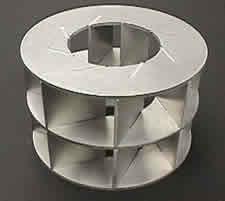
Contributing Writer
- FMA
- The Fabricator
- FABTECH
- Canadian Metalworking
Categories
- Additive Manufacturing
- Aluminum Welding
- Arc Welding
- Assembly and Joining
- Automation and Robotics
- Bending and Forming
- Consumables
- Cutting and Weld Prep
- Electric Vehicles
- En Español
- Finishing
- Hydroforming
- Laser Cutting
- Laser Welding
- Machining
- Manufacturing Software
- Materials Handling
- Metals/Materials
- Oxyfuel Cutting
- Plasma Cutting
- Power Tools
- Punching and Other Holemaking
- Roll Forming
- Safety
- Sawing
- Shearing
- Shop Management
- Testing and Measuring
- Tube and Pipe Fabrication
- Tube and Pipe Production
- Waterjet Cutting
Industry Directory
Webcasts
Podcasts
FAB 40
Advertise
Subscribe
Account Login
Search
Designing for abrasive waterjet fabrication
Forethought, flexibility can help cut corners
- By Dr. John H. Olsen
- May 4, 2004
- Article
- Waterjet Cutting
Designers need to be familiar with some abrasive waterjet machining features to minimize overall cost. Some of these concepts also may apply to laser, plasma and oxyfuel cutting.
Drafting Practices
All projects begin with a design, which usually is prepared with a CAD program. Almost all abrasive waterjet systems accept CAD data (usually a 2-D .dxf file) as input for generating the tool path that cuts the part. Carefully preparing an accurate CAD drawing saves time in setting the tool path and helps prevent errors that cause scrap. Specifically, follow these guidelines:
- Produce accurate drawings. Draw the part exactly to size in the CAD system. If a hole is to be 0.502 in. in diameter, draw it as 0.502 in. and not 0.500 in. with a dimension showing 0.502 in.
- Close corners. Be certain that corners are closed without gaps or overlapping lines ((see Figure 1).Even microscopic errors of this kind can foil automatic tool path generation routines. Most CAD programs provide snaps for joining drawing entities without these defects. Use them.
- Draw with lines and arcs. Many cutting machines directly accept .dxf files containing lines and arcs, but require an intermediate step to convert splines, polylines, blocks and text to lines and arcs before making the tool path. If you want to draw with these entity types, explode them to lines and arcs before exporting the .dxf file.
- Set tolerances and dimensions carefully and only when necessary. In general, it is not useful to spend time dimensioning and placing tolerances on a part to be made entirely by abrasive waterjet machining. The machine's path is the same no matter what tolerance is specified. An overall tolerance on how close the part must be to the theoretical line is useful for selecting which machine can be
used. On the other hand, features that must be controlled tighter than the overall tolerance should be toleranced separately, so that it is evident that a second operation must be performed, such as reaming a hole.
The speed along the path varies according to the surface finish required. For this reason, finish requirements should be indicated. This specification usually is done by using "layers" within the .dxf file and is specific for each waterjet machine. Learn how to specify surface quality for the particular machine you will be using.
Avoid manual dimensioning. If dimensions are required for some reason other than the abrasive waterjet machine, use the automatic dimensioning feature of your CAD system. A machine operator's worst nightmare is to make scrap because the .dxf file and the dimensioned drawing don't agree.
- Choose the right file formats. The .dxf file is the most popular format for exchanging 2-D CAD data. Unfortunately, there are hundreds of flavors of .dxf files, and you may have conversion problems. AutoCAD® release 12 .dxf files are the most popular, and almost all programs can import them. Avoid binary .dxf files because almost no one supports them.
If you have trouble reading a .dxf after it has been sent by e-mail, try using PK-Zip to zip it first. Some e-mail programs recognize a .dxf file as a text file and reformat it using rules that make it useless as a .dxf file.
Individual Part Design
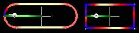
The speed at which an abrasive waterjet can cut depends on the shape of the part. Fine, sharp features cut more slowly than large, rounded features. Smooth, striation-free edges take longer to cut than rough severance cuts. Some guidelines follow for designing parts to save time later.
- Internal corners. An abrasive waterjet must slow down to make precise, sharp internal corners. By closing a slot with an arc rather than a square end, the cutting time can be reduced. This is true even when the path length is increased as in Figure 2):
a) Round Ends
Cut time = 0.832 minute
b) Square Ends
Cut length = 3.57 in.Cut time = 1.142 minute
Cut length = 3 in. - External Corners. The correct strategy for cutting external corners previously was the same as for internal corners; namely, radius the corners to decrease cutting time. Recently, however, the concept of corner passing has made it possible to make sharp corners by moving past the corner into the scrap at the full cutting speed until the lagging bottom portion of the jet has passed the
corner. Then the jet is moved back to the corner quickly and started on its new path. The result is a quickly cut, high-quality corner.
Check whether the machine you use has corner passing. If so, sharp corners are cut the fastest. Otherwise, design the corners with as large a radius as possible to save cutting time.
- Piercing. With each pierce of the material, you must wait for the jet to turn off from the previous cut, restart for the new cut, and then pierce the material. If there are holes near the periphery of a part, it often is faster simply to connect them to the outside rather than pierce them. Figure 3 shows a flange gasket made with this principle.
- Taper. An abrasive waterjet kerf is tapered. When the jet moves slowly, the kerf is widest at the bottom. When it moves fast, the kerf is widest at the top. The jet cuts thin materials at a high speed, and for this reason, thin materials have greater edge taper than thicker materials. Be sure that your design can tolerate this edge taper. If not, you can move slowly along the portion of the path that must be taper-free, or use a more sophisticated machine that tilts the head to remove taper while cutting at normal speed.
- Tabbing. Tabs on the part edge are used most commonly to hold the part in place while it is being cut. By using tabs, hundreds of small parts can be cut from a single plate unattended without the finished parts snagging the nozzle or falling into the catcher, where they are easily lost.
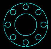
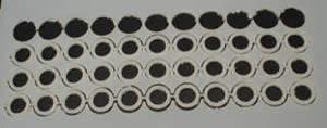
Tabs also are a useful way to store small parts to minimize handling. Storing in inventory, anodizing, and plating all can be performed on a single sheet of tabbed parts. Then, when the parts are needed, they are broken free like parts in a plastic toy model kit. See Figure 4.
Assembly and Weldment Design
Forethought about the entire design as an assembly or weldment also can save manufacturing time (see Lead Image). The shape flexibility and the precision possible with abrasive waterjet cutting permit self jigging assemblies and other useful features for easing assembly.
- Use tabs and slots to aid assembly. Some of the assembly techniques used in sheet metal work can be used with heavy plates cut with abrasive jets. Slots can be used to precisely receive tabs cut on the mating part. Joining is then achieved by one of three methods:
a) The tab extends through the mating plate and is twisted with a wrench to lock the two pieces together.
b) The tab is somewhat shorter than the plate thickness and is plug-welded into place.
c) The tab is somewhat shorter than the plate thickness and is tapped for bolting into place.
- Use a constant thickness. If all pieces of a weldment or assembly are the same material and thickness, they all can be cut from the same plate. Small parts can be nested within holes in large parts to save material, and parts for the entire assembly can be made in one setup, saving shop time.
- Make holes for fasteners and bearings. Abrasive jets make clean, precise holes that either can be tapped or reamed as soon as the part is removed from the machine. Bearings can be pressed directly into reamed holes. Tapped holes provide accurate location and eliminate the need to handle nuts and second wrenches during assembly. Square holes can be used in combination with carriage bolts as another method for eliminating second wrenches at assembly.
Time can be saved in piece-part manufacturing, assembly, and welding by using knowledge of the cutting process to its fullest during the design phase.
Taking Out Taper
Two ingredients are necessary for removing taper: a mechanism for tilting the jet and software that correctly anticipates the taper and drives the tilting head accordingly.
The tilting mechanism is attached to the XY table normally used without tilt. It is important that the center of rotation for the tilt be close to the point where the jet enters the top of the workpiece. Otherwise, keeping the jet entry point on the path would require large motions of the XY axes when tilt occurs.
The software includes a mathematical model of the cutting process, which anticipates the effects of the jet speed and automatically adjusts the jet motion by tilting the head to make a part with improved accuracy. Combining a jet-tilting mechanism with taper-compensating software produces taper-free parts in fractions of the time it takes to make them by just slowing down the process.
About the Author
Dr. John H. Olsen
21409 72nd Ave. S.
Kent, WA 98032
253-872-2300
Related Companies
subscribe now
The Fabricator is North America's leading magazine for the metal forming and fabricating industry. The magazine delivers the news, technical articles, and case histories that enable fabricators to do their jobs more efficiently. The Fabricator has served the industry since 1970.
start your free subscription- Stay connected from anywhere
Easily access valuable industry resources now with full access to the digital edition of The Fabricator.
Easily access valuable industry resources now with full access to the digital edition of The Welder.
Easily access valuable industry resources now with full access to the digital edition of The Tube and Pipe Journal.
Easily access valuable industry resources now with full access to the digital edition of The Fabricator en Español.
- Podcasting
- Podcast:
- The Fabricator Podcast
- Published:
- 04/16/2024
- Running Time:
- 63:29
In this episode of The Fabricator Podcast, Caleb Chamberlain, co-founder and CEO of OSH Cut, discusses his company’s...
- Trending Articles
AI, machine learning, and the future of metal fabrication
Employee ownership: The best way to ensure engagement
Dynamic Metal blossoms with each passing year
Steel industry reacts to Nucor’s new weekly published HRC price
Metal fabrication management: A guide for new supervisors
- Industry Events
16th Annual Safety Conference
- April 30 - May 1, 2024
- Elgin,
Pipe and Tube Conference
- May 21 - 22, 2024
- Omaha, NE
World-Class Roll Forming Workshop
- June 5 - 6, 2024
- Louisville, KY
Advanced Laser Application Workshop
- June 25 - 27, 2024
- Novi, MI