


Sales Manager
 |
| Figure 1 |
Orbital gas tungsten arc welding (GTAW) has been used in many industries since its introduction in the 1950s. Developed by the aerospace industry for welding small fittings to tubes, the process was limited by its large power supplies and cumbersome fixtures suited only to workshop applications. With the introduction of computerization 25 years ago, more modern, portable equipment has evolved.
However, this equipment almost always was meant for DC applications, so it couldn't be used with aluminum because it's difficult to weld with DC GTAW. In addition, components required meticulous cleaning before welding, as well as the proper gas mixture.
Today AC orbital welding power supplies make it possible to weld aluminum and aluminum alloys more successfully in a production environment.
GTAW uses either direct current electrode negative (DCEN), or forward polarity, or AC (see Figure 1). DCEN uses constant heat distribution, with two-thirds of the heat in the workpiece and the other third in the electrode. With AC, the heat is balanced with polarity switching at a preset rate of 50 to 200 hertz. You can adjust the AC balance and frequency to control the arc contour and, therefore, the weld profile.
The process creates an arc in an inert atmosphere between a nonconsumable tungsten electrode and the workpiece. This arc creates enough heat to melt the workpiece and create a weld pool.
An inert gas — usually argon — must surround the process. Some gas mixtures allow faster welding speeds and increased penetration and produce a cleaner weld bead. Most common gas mixtures are argon/hydrogen and argon/helium in varying ratios. The gas type depends on the material, application, and economic factors.
 |
| Figure 2 This oxide layer, also known as alumina, is so stable that it is purposefully formed during anodization as a way to protect aluminum subjected to an extremely corrosive environment, such as seawater. |
For AC applications, zirconiated tungsten electrodes commonly are used. You should select an electrode type that will provide a stable balled end when welding. The electrode will not sustain a pointed profile.
Typically, you need an AC GTAW power supply to obtain successful results when welding aluminum manually. Aluminum is difficult to weld because of the stable oxide layer that forms instantly on the aluminum surface even in minute oxygen concentration levels (see Figure 2).
Because of the difference in the melting points of the aluminum (660 degrees C) and of the alumina layer (2,000 degrees C), a wetting of the adjoining weld pools of the weld parts can't be accomplished in the presence of such a formidable and insoluble agent.
If you don't remove the initial oxide film immediately before welding, and if you don't remove the dynamically formed oxide layer during welding, it will be difficult to accomplish successful welding.
You can remove the oxide layer mechanically by scraping or bead blasting before and during welding by using an AC arc during the reverse polarity cycle (part negative and electrode positive) of the AC welding waveform. During the reverse polarity cycle, the negatively charged electrons emanate from the part surface toward the electrode. This blows the oxides off the aluminum part surface by the energy imparted on the oxides from the emanating electrons.
 |
The electrons arriving at the electrode surface during the reverse polarity phase impart additional high energy into the electrode that is absent in forward polarity, causing the tungsten to melt and ball. Without an aluminum surface oxide barrier, the molten puddles can flow and join together from each of the parts in the weld joint. The material then can be welded with little trouble.
You can optimize your weld bead profile by adjusting the AC balance (see Figure 3) and AC frequency (see Figure 4).
The AC balance control allows the AC wave pattern to be biased toward either predominantly electrode positive or electrode negative. By adjusting the balance of the waveform, you can control the amount of heat in the parent material. With the electrode predominantly positive, the material will have less heat input and, through the reverse polarity, produce more of a material cleaning effect. With the electrode predominantly negative, the material will have more heat input, and you'll achieve deeper penetration with less material cleaning.
A high AC frequency will cause the arc to constrict and, in turn, produce a narrower weld bead and profile. As the frequency lowers, the arc and weld profile become wider. The high frequency produces a stiffer arc, which makes it more stable in precise applications.
An orbital welding system has two main components: an orbital welding power supply to provide power and system control and an orbital welding head to rotate the torch or electrode and perform the weld cycle.
Power Supplies. Today's orbital welding power supplies can be used for all applications. The most up-to-date equipment can control welding current, rotation, wire feed, and gas flow with feedbacks from the weld head to maintain a consistent weld profile.
Some power supplies also have a built-in cooling unit that provides a liquid coolant to the sensitive parts of the weld head to eliminate heat buildup. Additionally, the units can store hundreds of weld procedures that detail the tungsten electrode, gas type and flow, joint preparation, parent material, and filler materials used. Others have data acquisition capabilities that allow weld data logs to be loaded to a PC card and transferred directly to a PC for interrogation or storage.
Modern power supplies also might include a function that helps reduce the amount of time needed to develop a suitable weld procedure for an application. Such a system takes tube size, material type, and gas used into consideration. Other standard features may include display panels, integral printers, fault sensors, key switch, and weld head recognition.
For AC applications, an AC/DC power supply offers the standard functions of a DC machine but has an AC generation module so you can also control AC frequency and AC balance.
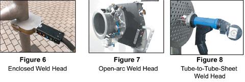 |
Weld Heads. Three common types of weld heads are:
 |
| Figure 9 Consumable Socket Insert |
Consumable Socket Insert. AC welding requires an initial current to produce a stable arc following arc strike. In thin-material welding, the starting energy often is higher than the level that the material can accept. As a result, the material melts away as soon as you strike an arc. To overcome this problem, you can use a consumable socket insert that enables this initial starting current without burning the material at the starting point (see Figure 9).
The consumable socket insert also allows you to join difficult-to-weld materials, such as the 6000 series, with an enclosed head. This is because the consumable socket insert can be produced from the filler material that normally would be used in wire-feed welding. With the filler metals being used as part of the setup, these materials can be welded without adding wire (see Figure 5).
The consumable socket insert also helps align the weld seam. It normally is fitted between the two components to be welded and located on the tube OD, thus providing suitable tube alignment.
Steve Purnell is sales manager, Orbimatic GmbH, Flosser Weg 17, 35418Busek, Germany, +49-6408-9026-0, fax +49-6408-9026-50, steve@orbimatic.co.uk, www.orbimatic.com.

The Tube and Pipe Journal became the first magazine dedicated to serving the metal tube and pipe industry in 1990. Today, it remains the only North American publication devoted to this industry, and it has become the most trusted source of information for tube and pipe professionals.
start your free subscription
Easily access valuable industry resources now with full access to the digital edition of The Fabricator.

Easily access valuable industry resources now with full access to the digital edition of The Welder.

Easily access valuable industry resources now with full access to the digital edition of The Tube and Pipe Journal.

Easily access valuable industry resources now with full access to the digital edition of The Fabricator en Español.
In this episode of The Fabricator Podcast, Caleb Chamberlain, co-founder and CEO of OSH Cut, discusses his company’s...


