


Senior Editor
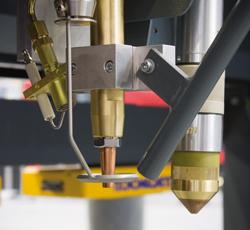
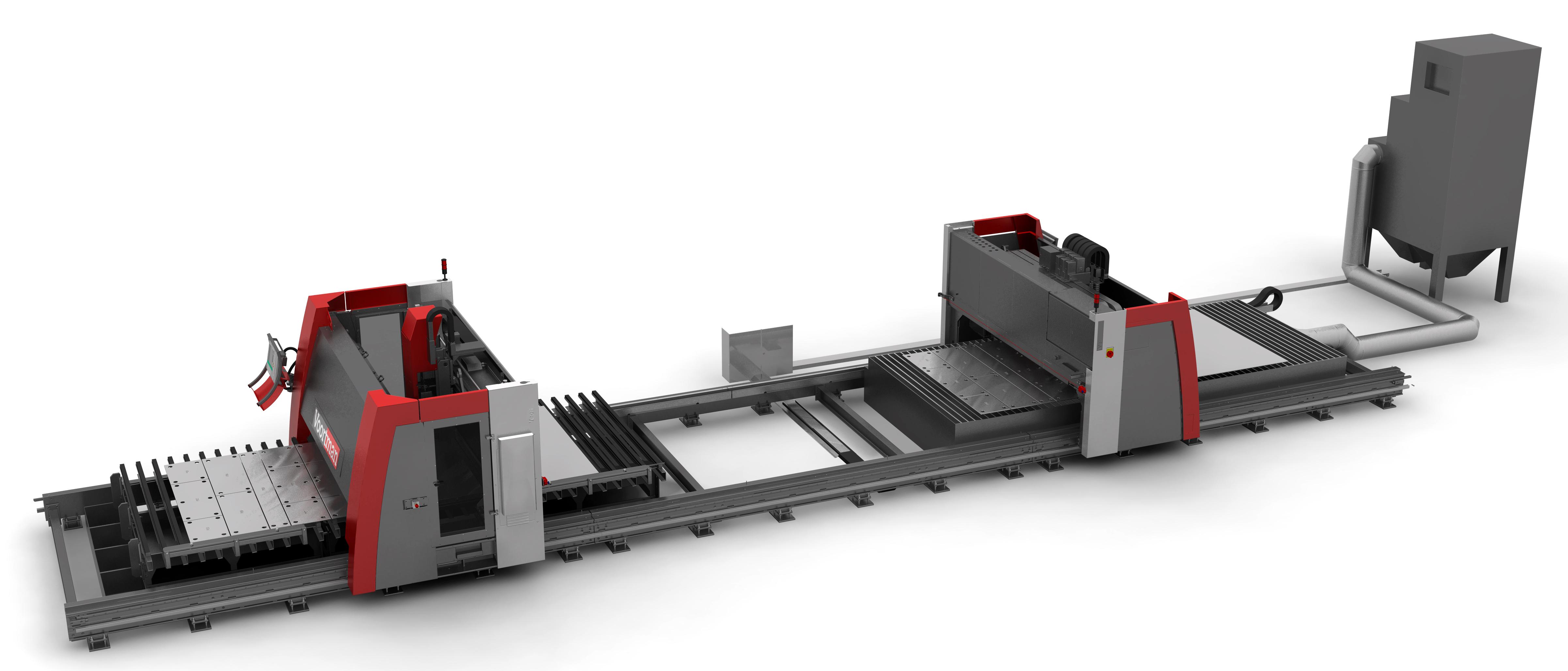
Figure 1: Combination machines—combining plasma, oxyfuel, drilling, and other processes—have helped plate and structural fabricators significantly reduce material handling and up productivity. Photo courtesy of Voortman Corp.
Any lean guru will tell you that most waste results from time spent moving and waiting for material. Those in lightgauge sheet metal work solve this problem in part with automated material handling. It’s why many have invested in towers that feed material into cutting systems.
Walk into a plate or structural fabricator’s shop and you probably won’t see such towers. Most standard-sized plates are just too heavy, so most have no other practical choice but to use the overhead crane. But that traditional approach is changing. Using roller conveyors and other methods, some have sped material handling directly. Then there’s the indirect method: reducing the number of operations.
More plate fabricators are investing in combination plate processing centers that handle all the cutting a heavy plate might require, including oxyfuel (for extremely thick plate), plasma cutting, milling, and drilling (see Figure 1 and Figure 2).The concept is simple: The more you fabricate in one setup, the less you handle the material.
Traditionally, an operator would use an overhead crane to carry plate to the burn table that would cut the part. Next he would get on top of the table and use the crane again to remove the heavy cut blank, and then stack the plate and move it to a secondary operation, such as tack welding and holemaking with a radial drill. What if somebody else was using the crane? Well then, he’d just have to wait.
“Ten years ago, that’s how many fabricators did it,? said Michael Sharp, president of Peddinghaus Corp., Bradley, Ill.
In recent years, however, plate and structural fabricators have strived to reduce handling time, and the combination plate processing center provided a way.
“The biggest advancement in recent years has been the fact that thermal cutting, punching or drilling, part marking, and scribing all have been combined into one CNC process,? said Tom Boyer, president of Ficep Corp., Forest Hill, Md. Plate goes in and completed blanks emerge, often with part identification and layout marks that show how the structural components fit into a whole.
As far as sequencing in combination machines, drilling and other machining work for interior part attributes and pilot holes usually happen first; then comes thermal cutting of interior components and the part profile. This follows logic. Cutting the profile first would set the blank free from the heavy plate, so something else would have to hold the plate in place.
Most of the sequencing is determined by nesting software, which minimizes scrap and the number of times a thermal torch starts and stops, to maximize torch consumable life. All this has led to edge starting (starting on the edge of a blank or in a predrilled pilot hole), common-line cutting (parts sharing a common edge in a nest), and chain cutting (or cutting multiple parts out of a nest without relighting the torch).
Wind towers require some large-scale, seriously thick-plate fabrication, and it doesn’t get much thicker than the tower’s base plate—often 5.5 inches (that’s right, inches).
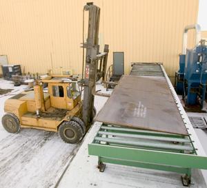
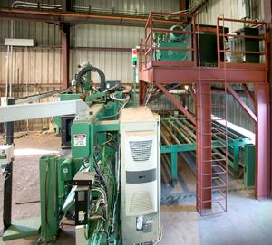
Figure 7: This structural fabricator minimized space under roof by storing metal outside and feeding plate via conveyors into the building and directly into the metal processing center. Photo courtesy of Peddinghaus Corp.
One base plate fabricator previously spent a lot of time cutting plate with an oxyfuel machine. Operators would install a large cutting tip to pierce up to 70 holes. Then they would remove the spatter from the top of the plate to attain a quality cut, replace the torch cutting tip with a smaller one appropriate for the job, and oxyfuel-cut every 2.625-in.-diameter hole; finally, the torch would cut the profile. This took three to four hours to cut a single base plate.
Adopting combination technology—a machine combining thermal cutting and drilling—reduced that time to 30 minutes. The machine drilled pilot holes, then cut the remaining metal with oxyfuel—no piercing required.
“Pilot holes make the oxyfuel process a lot more reliable,? said John Johnson, vice president and general manager of Farley Laserlab USA, Rockford, Ill. “We’re not worried about overheating the material. We just spend a few seconds preheating the edge, and then start cutting.?
In 5.5-in.-thick material, that’s saying something. Not only do pilot holes reduce overall cycle time, they also prolong the life of torch consumables, which can take a beating from molten-metal blowback during piercing.
Some machines also have milling and threading heads that allow for the cutting of pockets and other geometries in thick plate. This also helps in meeting some tight tolerances. A torch can rough-cut an irregularly shaped hole, and the milling head can finish the edges to the required tolerance. Such milling may require some extra effort to hold the material steady, such as tack welding the plate to the table, but recent machine designs are making precision milling easier (see Figure 3).
“Machines now use what we call a ‘miniaxis,’? Johnson explained.
These machines have a dual-beam design for rigidity. From this are attached various “feet?—extensions from the beam that hold the cutting implement, be it a drill, mill, or torch. A milling operation uses a foot that is cylindrical, several feet tall, and a foot or so wide. From this, a large pneumatic hold-down fixture descends onto the plate, creating a 10- by 10-in. work envelope. The milling head then moves in X and Y within that work envelope. The machine’s foot actually doesn’t move. As a magazine-style automatic tool changer (analogous to ones found on conventional machining centers) switches out tools, the pneumatic clamp stays put to ensure positioning accuracy. In a sense, the plate processing center briefly turns into a vertical machining center.
“The fact that the machine holds the plate down without moving the foot allows it to add machined features to the part,? Johnson said.
Some machines now have separate tables and a magnetic material handling system to drill and thermal-cut plate simultaneously.
Introduced this year, these machines use two bridges that move between one table for drilling and tapping—with a magazine-style tool changer (see Figure 4)— and another table for oxyfuel and plasma cutting. Adrian Morrall, president of Voortman USA Corp. in Manteno, Ill., explained: “It’s a new concept. The machine drills the plate first. Then these two bridge frames come together. Each bridge has magnets that pick up the drilled plate and move it to the burning table on the other side.?
The thermal cutting table has a CCD camera that detects part attributes. This means the thermal cutting’s accuracy isn’t affected by the plate’s edge condition from the mill. Instead, the machine measures cut lines in relation to previously drilled holes. Meanwhile the next plate is moved into position for drilling (see Figure 5).
For extremely heavy-plate fabrication, such as that 5.5-in.-thick wind tower base plate, the overhead crane may be the only practical material handling option. But for thinner plate, there are alternatives.
Certain plate cutting machines offer material load and offload systems. Essentially, the sheet load and offload technology of laser cutting has been adapted for the thermal cutting and drilling of plate.
As Johnson explained, such systems can now carry up to 1.25-in.-thick plate. Specialized lifters transfer the plate to a fork system, which moves over to the cutting table and lowers the plate onto the slats. The material is clamped in place before the machine processes it. Afterward the forks lift the plate—cut components and all—and sets it onto an offloading table. “You can have multiple load and unloading stations in this setup,? said Johnson, who added that such systems can be built with flexibility in mind. Some modules allow automated load/unload of plate 1.25 in. thick and less, and others allow manual loading of thicker plate.
In the structural fabrication arena, plate cutting centers have evolved to the point where thick plate flows in and out continuously. It’s almost like a coil feed, except instead of coil you have a series of heavy plates. In such a setup, the plate moves in on rollers in the X direction (the long direction). At the machine, the plate progresses between the upper and lower rollers, which move the plate back and forth inside the machine. The rollers stop the plate for drilling and tapping, and then move it back and forth in X again as the thermal cutting torch moves in the Y.
“The combination of those two let’s you process anything you want as far as shapes, contours,? Peddinghaus’ Sharp explained. “The plates drop off at the end of the machine and don’t have to be manually unloaded.?
He added that such combination technology supports another trend in structural fabrication: reducing space under roof. Because such machines accomplish so much in a small footprint, they’ve helped spawn a new way of thinking about shop floor layout. Fabricators can store material outside, place plates and beams on rollers, which transport the material inside a small structure housing one or more pieces of fabricating equipment. This not only increases material handling efficiency, but also eliminates thousands of square feet of inside shop floor space, saving heating and maintenance costs (see Figure 6 and Figure 7).
A fast primary cutting center doesn’t mean much if it just produces a bottleneck in downstream operations. This is why efficient plate processing and material handling really is only half the story. The other half is the ability to track parts through production so that the plate reaches downstream operations at the right time, to minimize work-in-process.
In sheet metal and plate fabrication, material resource and enterprise resource planning (MRP and ERP) software and other shop management software have answered the need. In structural fabrication, MRP packages such as FabTrol have offered similar benefits. However, part flow and part tracking get more complicated for structural fabricators, for obvious reasons: They process beams and plates that become part of an entire building.
Enter building information modeling, or BIM, a concept that strives to get all parties—the architect, engineers, general contractors, mechanical contractors, HVAC, specialty contractors, structural fabricators, and others—on the same page. For the structural fabricator, BIM allows the shop to derive all machine programming data from one master file, a comprehensive 3-D model.
Has the BIM approach gotten to the point at which all parties involved, from the architect to the steel fabricator, work off the same BIM 3-D file, perhaps placed on a shared Web site? No—at least not yet. According to Mark Allphin, steel business manager of BIM software provider Tekla Inc., Kennesaw, Ga., that ideal just isn’t practical yet. But BIM does give all parties the opportunity to develop their own BIM CAD file of the building, then export it into a neutral file format and post that on, say, an FTP site.
Where the concept shines for structural fabricators is in intelligent data exchange between the BIM software, CNCs on the machine tools, and shop floor MRP and ERP software. Today data flow can happen seamlessly, with the BIM software exporting files directly to machine tools.
Several machine tool vendors are working with software vendors to develop proprietary file formats that add more intelligence to the part program. For instance, certain machines now can communicate with BIM software via proprietary files that have an XML, or extensible markup language, structure. “When you download an XML-type file to a machine, you’re not just downloading information for a plate,? Ficep’s Boyer explained.
Such files don’t just have lines, such as standard drawing files. The lines mean something. “We’re working with more information. The files show material grade, profile shape, finish type. These capture so much data beyond a typical drawing file,? Allphin said.
Working under BIM, “you’re downloading all the information that relates to that plate, including scribing information,? Boyer explained. The machine cuts, copes, and scribes the part number and layout information so the fitter will know exactly where to attach the end plate to a column or other joining members.
“Now we’re really exporting information about an assembly, not just information about one column or one plate,? he said.
Data flow is no longer a one-way street either, Tekla’s Allphin said. Machine tool CNCs and ERP/MRP software now can feed information back to the BIM. This allows the 3-D building model to embed a fabricator’s job status information, showing whether this end plate or that column is on schedule or behind, depending on the color assigned to the component.
A manager can glance at the model and know immediately, by looking at the colors of different components, where manufacturing stands on the shop floor.
BIM is the latest piece to be added to the structural fabricator’s productivity puzzle. The concept eliminates those islands of automation, which is a good thing; blazingly fast processing of a thick plate on a multiprocess machine means nothing if it’s the wrong plate. By working in concert, advancing machine tool and software technologies help shorten the manufacturing time not just for this plate or that column, but for the entire assembly.


The Fabricator is North America's leading magazine for the metal forming and fabricating industry. The magazine delivers the news, technical articles, and case histories that enable fabricators to do their jobs more efficiently. The Fabricator has served the industry since 1970.
start your free subscription
Easily access valuable industry resources now with full access to the digital edition of The Fabricator.

Easily access valuable industry resources now with full access to the digital edition of The Welder.

Easily access valuable industry resources now with full access to the digital edition of The Tube and Pipe Journal.

Easily access valuable industry resources now with full access to the digital edition of The Fabricator en Español.
In this episode of The Fabricator Podcast, Caleb Chamberlain, co-founder and CEO of OSH Cut, discusses his company’s...


