


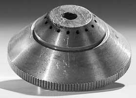
Starting from scratch
Plasma arc cutting basics and operator guidelines
 |
| A notched shield like this one will cause poor cut quality. |
The key to obtaining high cut quality and long consumable life when cutting with plasma lies in both a general understanding of plasma and being aware of the process's fundamental operating guidelines. Knowledge of both allows operators to evaluate the cutting process and diagnose problems that may be occurring in the plasma torch.
In the Beginning
Plasma cutting occurs when a beam of ionized gas heats an electrically conductive material beyond its melting point and flushes molten metal through the kerf of the cut. An electrical arc is produced between the electrode in the torch and the piece of metal being cut by ionizing a beam of pressurized gas to a temperature between 14,000 degrees and 26,000 degrees F.
 |
| Figure 1 A good torch design facilitates coolant flow. |
Plasma cutting generally is used for metal thicknesses from 0.125 inch to 2.000 in. (3.175 mm to 50.800 mm). The kerf width of the cut is approximately 1.5 to two times the size of the nozzle orifice used, which varies depending on the current in use. Common plasma gases used for cutting are air, nitrogen, argon/hydrogen, and oxygen. The assist gas generally is air, carbon dioxide, or nitrogen. In some instances, the assist gas is replaced with water, such as in water-injection torches. Both the plasma gas and assist gas are determined based on the type of material being cut, the cost of operation, and the cut quality required.
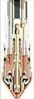
Torch Design, Consumables
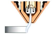
The plasma torch is designed so that various gases, torch coolant, water (if applicable), and electrical current can flow through the torch simultaneously without adversely affecting one another. Consumables for the plasma torch include the electrode, nozzle, gas distributor (swirl ring or gas baffle), and shield. Some new torch designs include features such as a stainless steel sleeve to protect parts from the plasma arc and the radiant heat produced. They also may include an internal sleeve that is both screwed and glued to the stainless steel sleeve to prevent misalignment of internal torch components. The electrode and nozzle generally are cooled by the torch coolant that flows through the electrode and around the nozzle to optimize life (see Figure 1).
The Electrode
The plasma arc initiates from the emitting element that is inserted into the tip of the electrode, causing the material to wear back slowly. Tungsten is the emitting element used for electrodes in nonoxidizing atmospheres, while hafnium is the preferred element when cutting with oxygen.
 |
| Figure 2 These electrodes with a silver casing around the hafnium are in failure mode. |
Electrode failure occurs when the emitting element has worn back so far that the arc begins to emit off of the surrounding copper or silver casing. Once the plasma arc contacts the electrode casing, it can quickly melt and destroy the entire electrode assembly. It has been shown that an electrode with a silver casing allows for better cooling of the hafnium insert, and that the hafnium can be worn much deeper than a standard copper electrode. Figure 2shows the failure mode of two electrodes with a silver casing around the hafnium.
Nozzle Design
The nozzle design is the key to obtaining optimal performance from the plasma torch. The nozzle focuses the stream of plasma to produce the cut. The alignment of the electrode and nozzle, as well as the condition of the gas distributor, is critical to obtaining good cut quality. Nozzles are designed so that the orifice is slightly larger than the stream of plasma being focused. This allows the nozzle to contain and focus the vortex of plasma without being affected by it.
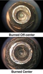
The length of the nozzle bore is directly related to the cut quality achieved. A long bore generally yields a high-density arc and superior cut quality while a short bore generally yields relatively poor cut quality but extended life. The nozzle may become externally damaged because of metal spatter and arc stretching, as shown in Figure 3. The nozzle also may be internally damaged because of a gas flow problem (gas pressure, swirl intensity, or damaged gas distributor) (see Figure 4).
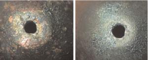 |
| Figure 3 External nozzle damage can be caused by spatter, molten metal, and arc stretching. |
 |
| Figure 4 Internal nozzle damage can be caused by a torch that burns off-center or by a gas flow problem. |
Gas Distributors
Electrode life is influenced by the pressure of the plasma gas. High pressure causes the electrode to wear quickly, while lower-pressure gas allows the electrode to last longer. The intensity of the gas vortex created by the gas distributor directly affects the gas pressure of the plasma gas. A high-intensity vortex constricts the plasma arc, increases the pressure, and yields high cut quality. A low-intensity vortex provides longer electrode life but produces a less optimal cut.
The condition of the gas distributor directly affects the vortex of plasma gas. If the gas distributor becomes clogged or damaged, it will not funnel the plasma gas (and in some torch designs, the assist gas) properly. If the vortex of plasma gas is not perfectly centered with the nozzle orifice, the plasma arc will burn off-center and damage the bore of the nozzle (see Figure 4).
The shield is used to protect the nozzle from damage during the cutting process. It may or may not have assist gas holes around the orifice of the shield to help blow metal spatter away from the torch. However, if the orifice of the shield gets damaged, it will affect the cut quality by disrupting the flow of ionized gas.
In some newer torch designs, the orifice of the shield is designed in such a way that it helps the assist gas constrict the plasma gas to create a denser plasma arc. These shields, however, are more susceptible to damage than standard shields, and a notched shield produces a poor-quality cut. Shields generally become damaged because of low assist gas flow, piercing too close to the plate and becoming submerged by puddles of molten metal, and arc stretching (seeintroductory image).
 |
| Figure 5 When a torch cuts off the plate, arc stretching is the result. |
Arc Stretching
Arc stretching occurs when the electrically conductive material being cut is no longer directly under the torch; when the torch motion is too slow following the pierce; whenever a lead-in or lead-out is programmed incorrectly; or when the arc-off signal is delayed. In these instances, the plasma arc is forced to "stretch" to one side or the other to reach the material, which forces the plasma arc to cut into the side of the nozzle orifice (see Figure 3).
The most common form of arc stretching is when an operator trims off a sheet of material, and the torch is allowed to cut off the plate (see Figure 5). It also occurs on plasma punch presses when holes are punched and the torch is programmed to start at the center of the punched holes.
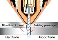
Cut Direction
The direction the torch is programmed to cut may be influenced by factors such as the nesting of parts to be cut and the number of torches on the table. However, regardless of the direction chosen to cut, it is crucial that the correct type of gas distributor be used.
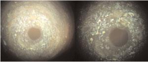
A gas distributor is designed to produce either a clockwise (cc) or counterclockwise (ccw) swirl pattern. This is important because the right side of the cut is the good side when using a clockwise swirl pattern (see Figure 6), while the left side of the cut is the good side when using a counterclockwise swirl pattern.
 |  |
| Figure 6 The good side of the cut has little to no bevel angle, while the scrap side of the cut usually has a bevel angle of 6 degrees or more. | Figure 7 Many factors determine a bevel angle, including cut height, torch speed and squareness, and bowed material. |
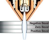
Bevel Angle
A part's bevel angle primarily depends on the cut height and speed of the torch. However, bevel angles also will occur when the torch is not perfectly square with the material being cut, when the cutting material is bowed, when the wrong gas distributor is used, or when the nozzle is damaged. If the cut height is too low, the bevel angle will be negative, and if it is too high, the bevel angle will be positive. Similarly, if the speed is too slow, a negative bevel angle will be produced; if the speed is too fast, a positive bevel angle will be produced. Therefore, to correct a negative bevel angle, the torch height should be increased or the speed should be increased. To correct a positive bevel angle, the torch height should be decreased or the torch speed should be decreased (see Figure 7).
Lead-in, Lead-out
Programming the correct lead-in or lead-out at the beginning and end of a part can be quite difficult, because the lead-in or lead-out is directly related to the thickness of the material, the cutting speed of the torch, and the size of the part or hole being cut. The lead-in should begin approximately 0.25 in. to 0.5 in. before the beginning of the part.
The torch pierces the plate, ramps up speed and current, cuts the profile at the correct height and speed, freezes the torch height approximately 0.25 in. to 0.5 in. before the end of the cut (so that the torch does not dive into the plate when the part drops out), and cuts just far enough so that the bottom edge of the part (or hole) is cut. The lead-out is generally between 0 in. and 0.25 in., unless the material is so thick that it requires a longer lead-out.
Cutting Sequence
Cutting holes can be challenging because either a dimple or bump will occur when the lead-out is too long or too short. A dimple occurs when the lead-out is programmed slightly too long, and a bump occurs when the lead-out is programmed slightly too short.
For a good-quality hole, the hole diameter should be no less than twice the material thickness. Also, the gantry must be able to handle the accuracy and precision required. If the drives and motors cannot move the gantry without causing vibration, then it is almost impossible to cut a hole that is both accurate and precise.
The cutting sequence for a hole is as follows: The torch pierces toward the center of the hole to be cut, ramps up speed and current, cuts the hole at the correct height and speed, and cuts just far enough so that the bottom edge of the hole is cut.
Antispatter Pros and Cons
Antispatter is used on shields to prevent metal spatter from sticking during piercing or cutting. It is crucial that the shield is removed from the torch when applying antispatter, and that only a thin coating of it is used. The most prevalent problem with using antispatter is that too much is used and that it is applied incorrectly. If too much antispatter is placed on the shield, the compound can be sucked into the torch when the torch begins to fire because there is a pressure change between the internal and external components of the torch that allows substances (vapor, oil, debris) to be drawn back into the torch.
Piercing Thick Metal
Piercing metal that is 1 in. thick or thicker can cause catastrophic failure of consumables if done incorrectly. When thick material is pierced, a large amount of molten metal accumulates around the front of the torch that can cause bridging between the shield and plate, causing a short circuit.
Several techniques are used to help minimize damage to the front of the torch during piercing. Initially the torch height should be set approximately 0.5 in. above the plate during the pierce to protect the front of the torch from the molten metal created. The assist gas pressure and flow also should be checked and set correctly. The initial cut height should be set between 0.25 in. and 0.5 in. to give the torch more clearance from the plate following the pierce.
Piercing Sequence
Evaluating the piercing sequence of the torch and adjusting the parameters accordingly is the best way to avoid bridging and consumable failure. If the procedure outlined previously fails to solve the problem, several other techniques are available, such as a double-shot pierce and a creeping pierce.
In a double-shot pierce, the hole is initially pierced, and the torch stops cutting so that the operator can manually remove the slag. The torch pierces again on the edge of the hole and begins cutting. In a creeping pierce, the torch pierces and moves forward slowly so that the molten metal is blown out of the gouged cut behind the torch. The torch begins cutting once the torch pierces completely through the material.
Height Settings
The pierce height, cut height, and arc voltage-controlled cut height are separate settings that need to be understood and set correctly to achieve optimal cutting performance. The pierce height is the initial height of the torch while it pierces through the material, and it is generally set between 0.25 in. and 0.5 in. Once the torch pierces the material, the torch lowers to its initial cut height, which is a fixed height that is set between 0.125 in. and 0.25 in. (see Figure 8).
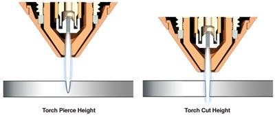 |
| Figure 8 The torch pierce height is generally twice the torch cut height. |
The torch cuts at the fixed cutting height briefly before the arc voltage-controlled cutting height takes over. The arc voltage is set so that the cutting height remains the same throughout the duration of the cut. Arc voltage is used to control the torch cutting height so that the torch is allowed the freedom to move up and down accordingly to compensate for bowing of the material.
Voltage is defined by Ohm's law, V = IR; where V is the voltage, I is the current, and R is the resistance. A torch height control (THC) system is designed using this law so that a given voltage will yield a specific cutting height.
However, because the emitting element of the electrode wears out during the cutting process, the voltage must be increased continually to compensate for the electrode wear. Otherwise, the cut height of the torch will decrease in relation to the wear of the electrode, causing consumables to fail prematurely (see Figure 9).
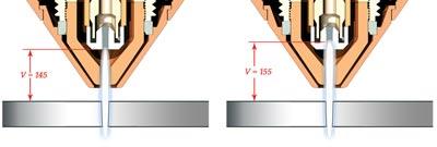 |
| Figure 9 This illustration depicts arc voltage-controlled cut height. |
To compensate for the electrode wear manually, the voltage can be increased in 2-V increments throughout the course of cutting. A 5-V adjustment in arc voltage is equivalent to a height increase of 0.125 in.
Tex Whiting is a product specialist for the Centricut brand team at Hypertherm, Two Technology Drive, West Lebanon, NH 03784, 800-752-7623, www.centricut.com.
About the Author
About the Publication
subscribe now

The Fabricator is North America's leading magazine for the metal forming and fabricating industry. The magazine delivers the news, technical articles, and case histories that enable fabricators to do their jobs more efficiently. The Fabricator has served the industry since 1970.
start your free subscription- Stay connected from anywhere

Easily access valuable industry resources now with full access to the digital edition of The Fabricator.

Easily access valuable industry resources now with full access to the digital edition of The Welder.

Easily access valuable industry resources now with full access to the digital edition of The Tube and Pipe Journal.

Easily access valuable industry resources now with full access to the digital edition of The Fabricator en Español.
- Podcasting

In this episode of The Fabricator Podcast, Caleb Chamberlain, co-founder and CEO of OSH Cut, discusses his company’s...


