


President
Editor's Note: This is the third in a series of seven articles that identify and define the need for a new theory on the net shape processes (of which draw forming is one) and that explain the general content and configuration that new theory must have.
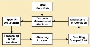 |
| Figure 1 The classic feedback control loop measures process output, compares the measurement with ideal conditions, and makes adjustments to process inputs to enhance performance. |
As discussed in Part II in this series, the outputs, the ideal conditions, and the process input variables in draw forming are not necessarily measured with the same units, and the measurements used do not have the same conceptual meaning. Hence, the classical feedback control loop (see Figure 1) breaks down.
How can the metrics be connected?
The connections between the product conditions and the processing input variables for draw forming (or any net shape process) must be made through one or more intermediary transformation characteristics.
A transformation characteristic is a characteristic of the material being shaped that is changed in a mathematically known way through the application of energy.
For draw forming, the transformation characteristics are plastic strains (stretching) and displacements (sliding). All the die can do to the sheet metal is to stretch it and slide it across the die face. So all product requirements must be redefined as the changes (or transformations) required of those two characteristics.
To avoid splitting, the strain pair (each strain has a major and minor value) must not exceed some limiting value. That limiting value is measured and diagrammed with the forming limit diagram. The diagram is a limiting line on a graph of major versus minor strain.
The forming limit diagram should be part of the material's specification and certification. The size of the strains can be measured on a formed part with a process called circle grid analysis and plotted on the forming limit diagram to assess the "healthiness" of the formed part.
During part and die design, the magnitude of the strains can be predicted with a finite element simulation and compared with the forming limit diagram. However, to compute the magnitude of the strains, the computer must make many calculations in which stresses are converted to strains and strains are converted to stresses. That can be done only if the shape of the stress-strain curve from the tensile test is known.
Fortunately, the stress-strain curve for most sheet metals can be represented by a formula commonly known as the power law, so only the K and N coefficients of that equation, plus the yield strength and the R-bar value, need to be provided by the material supplier.
Wrinkles form when the forming stresses become negative. This condition invariably is in the direction of the minor strain, but does not necessarily equate to negative minor strains.
Once the amount of straining is specified, calculated, or measured, the stresses can be calculated and evaluated for wrinkling if the parameters of the stress-strain curve are known. Target strain values can be assigned that will not result in negative forming stresses.
The basic shape is imposed by the shape of the die, but as the forming stresses relax, the part can move because of springback.
If all the forming stresses are positive and relatively uniform in magnitude, the part will shrink a predictable small amount, but not change shape. So it is important to design the die to impose strains throughout the part.
The calculations for predicting springback are the same as those for calculating stresses, so it is just a matter of watching to be sure that the stresses are fairly uniform. Stresses are not proportional to strains, so the magnitude of the stress is not obvious from the magnitude of strain. These considerations usually drive the designer to specify some minimum target strain values somewhere in the interior of the part.
The yield strength of the material increases as the material is strained. Therefore, if a material must have a specific yield strength when in service in a consumer product, the fabricator often can start with a lower-strength, more formable sheet material. The stress calculations will show what that new yield strength will be, and the necessary strains can become target strains to be achieved somewhere within the part.
The amount of thinning also is a part of the calculations, so when a minimum thickness must be maintained, the target strains to do that also can be determined.
Impact, skid, and draw lines result when the material being formed slides across the face of the die, so the amount, and direction, of the sliding motion (or displacement) must be evaluated.
If these lines are objectionable, the amount of sliding motion must be controlled. There is always a point in the interior of the part that does not slide across the die, and the design of acceptable sliding motions will determine where that point must be.
There is a relationship between the sliding motion and straining, so if the sliding motion must be somehow limited, it can result in limitation on the target strains in various locations on the part.
 |
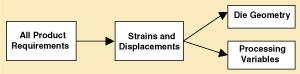
| Figure 2 Product requirements must be redefined into the changes (transformations) that must happen to the material strains and displacements (transformation characteristics) to meet those requirements. |
Product requirements must be defined in the changes (transformations) that must happen to the material strains and displacements (transformation characteristics) to meet those requirements (see Figure 2). The transformations are accomplished through the application of energy, and the calculations compute the energies.
These strains and displacements become the "ideal" conditions to which the measured output of the process is compared for the classical feedback control loop in Figure 1. That means that the process output must be determined by measuring the strains in the stamped part.
The various product requirements can cause conflicting needs for target strains and displacements. Such conflicts must be resolved, because at any one location the material can be strained only to one major and one minor strain and may have arrived at that location by displacing from another location. If the conflict cannot be resolved, some product requirements cannot be achieved.
The design of the die face, often called the binder development, can proceed once its purpose and requirements have been defined. Basically, the addendum shape (around the outside of the part), the draw beads, and the wrap shape must all be sized to impart the correct force and to allow the correct displacement into, or out of, the part at each point around its perimeter.
The objective of designing these die features is to force the target strains and displacements into the sheet metal, not to prevent splits and wrinkles. A design methodology complete with calculations can determine all feature sizes.
As the sizes of the die face features are being calculated and fitted together, the processing conditions are established:
These processing conditions are collected into the press setup and operating instructions.
 |
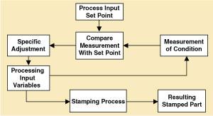
| Figure 3 Die face geometries and the set points for processing variables are calculated from the target, limiting strains, and displacements. |
The connections between the product requirements and the processing input variables have now been made (see Figure 3).
The process of establishing connections between the product requirements and the process input variables is quite different than for the non-net shape processes, in which the connections are generic, direct, and often obvious.
Once the die geometries and processing set points have been established, the actual operation of the press line can be put into a process control mode. The classical feedback diagram in Figure 1 is for quality control, because the quality of the output product is being measured.
 |
| Figure 4 Once the die geometries and processing set points have been calculated by working through the strains and displacements, a true process control mode of operating can be instituted.. |
Since the relationship between product quality and process inputs cannot be made, the corrective adjustments are based on experience or trial and error. Once the die geometries and processing set points have been calculated by working through the strains and displacements, however, a true process control mode of operating can be instituted (see Figure 4).
It is not necessary to check the condition of the actual product (except on a statistical sampling schedule), because it will be satisfactory if all the inputs are correct.


The Fabricator is North America's leading magazine for the metal forming and fabricating industry. The magazine delivers the news, technical articles, and case histories that enable fabricators to do their jobs more efficiently. The Fabricator has served the industry since 1970.
start your free subscription
Easily access valuable industry resources now with full access to the digital edition of The Fabricator.

Easily access valuable industry resources now with full access to the digital edition of The Welder.

Easily access valuable industry resources now with full access to the digital edition of The Tube and Pipe Journal.

Easily access valuable industry resources now with full access to the digital edition of The Fabricator en Español.
In this episode of The Fabricator Podcast, Caleb Chamberlain, co-founder and CEO of OSH Cut, discusses his company’s...


