


Senior Application Engineer
Editor’s Note: This article is adapted from Glen Shuldes, “Setting yourself up for success, dealing with failures, and changing your future,” presented at FABTECH®, Nov. 9-12, 2015, Chicago.
The punch press is one of the most mature technologies in metal fabrication, and yet it’s still one of the most misunderstood. Modern machines and tooling have turned the punch press into the Swiss army knife of the fab shop. It punches holes, just a few here and there or in a dense perforation. It cuts large panels. It forms louvers, embosses, and other complex shapes, and in some cases bends flanges several inches high.
Still, because the punch press can do so much, processing variables abound, and if they’re not accounted for, part quality and throughput can suffer. Understanding a few punching fundamentals can go a long way in ensuring that the multitude of processing variables remain well under control.
Walk into a fab shop and you’ll likely see technicians working with CAD. They’re transforming a drawing into a part that can actually be made out of sheet metal. A big part of this is taking into account bend radii.
Just as bends made on the press brake require radii, so do forms on the punch press. These realities, while obvious and virtually second nature to most fabricators, may not be so readily apparent to part designers, especially those who don’t work regularly with sheet metal.
Consider the embossed hat section with a 0.500-in. flat section, a 0.200-in. height, and a 45-degree emboss angle, as shown on the left in Figure 1. It’s simple to draw on a computer, but it’s impossible to manufacture out of a single piece of sheet metal. Sheet metal forms to a radius, and something has to give. So we usually start with defining the part’s design intent and the critical dimensions required for that intent.
Yet another variable is material thickness. If, say, a part designer specifies 16 gauge, that’s fine, but depending on the source, a single material gauge can vary 0.005 in. or more. Many designers specify the “top of sheet to top of form” as a critical dimension. But if a fabricator needs to hold the overall dimension, from the bottom of the sheet to the top of the form, problems arise as material thickness varies ever so slightly from one lot to another. The same thing applies to tensile strengths, which also can vary slightly.
By default, solid CAD models of formed sheet metal parts usually have slightly more volume than the flat dimension. This doesn’t reflect what really happens at the punch press. Even though a formed part has more surface area (which is why the solid model adds the volume to the part), it actually has the same volume because of material thinning, which typical modeling software doesn’t take into account.
Although an operation like flange forming resembles panel bending or folding, with one bend radius being folded upward, most form tools on the punch press perform an operation that resembles some kind of drawing operation in stamping.
For instance, as in drawing on the stamping press, forming an emboss on a punch press draws material from surrounding areas, which can cause distortion in holes or other nearby features. Unlike a stamping press, a punch press can’t clamp a large area in place during the forming process. And you can’t build in springs or nitrogen cylinders to apply pressure before forming starts. A simple louver may not require a lot of pressure, but a wide emboss in thick material may require significant force. In short, the limits of the punch press need to be taken into account.
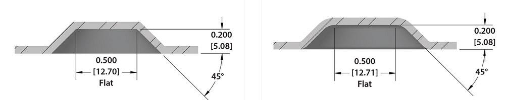
Figure 1
The form on the left is impossible to make out of a single sheet, because embossments require radii. This fact, obvious to most fabricators, may not be obvious to those who don’t work with sheet metal regularly.
That said, punch press technologies have changed in recent years, and some have the ability to apply tonnage before a form is created. For instance, a machine may be able to apply tonnage with the upper ram before the lower ram pushes the die upward to form the emboss. Moreover, machines with a stationary die top (as opposed to a moving die top) can hold the sheet with all the force provided by the upper ram.
This creates a situation closer to that of the stamping press, which can control clamping pressure so that the material being formed draws a little, but not so much as to cause distortion. A punch press still doesn’t have as much available pressure or control of that pressure as a stamping press does, but new tooling and machine technology certainly has opened up more forming potential at the punch press.
The suction created during the deformation of the slug during piercing causes the slug to stick to the face of the punch. Lubrication can also make the slug stick to the face. To prevent the slug from sticking, you need to break that suction.
One way is to cut slots into the face of the punch, which mitigates that suctioning effect. Another way is to use a punch with a hole drilled in the center and a spring-loaded steel or urethane pin inserted into it. When ejector pins fail, you can try pulling them out to create a kind of “ported” punch; the empty hole by itself can help break some suction (see Figure 2).
You can also use punches with a “rooftop,” or high point on the punch face, known as having a “shear” on the punch tool. When the slug contacts this kind of tool, it tends to naturally spring back and away from the punch face.
In the die, you can use slug retention systems, including a die with a “negative-positive” geometry (see Figure 3). By having a narrower diameter at the top of the die, these systems retain the slug once the punch ascends on the return stroke. The punch needs to descend far enough into the die for this to work consistently, but for the most part these systems are very effective.
If you don’t have a die like this on hand, you sometimes can use a Rocklinizer® or similar welding tool to lay a bead around the perimeter of the die opening. This has a similar effect as the dies described previously: It makes the die opening smaller and so helps retain the slug. Alternatively, you can use a small diamond file to put small notches in the die opening.
When pressure and heat get high enough, pieces of the workpiece material adhere to the punch—a problem known as galling.
To prevent it, first make sure you abide by a fundamental rule of engineering: Never have two pieces of the same grade of material rubbing against each other. Just as the cam in a car engine is made of different material than the valves and the lifters, so too should the punch be made of a material different from the workpiece.
D2 used to be a common material for punch tooling (though it’s not as common these days), but the last thing you wanted was to punch a D2 tool into stainless steel. If you did, galling probably resulted, because both stainless steel and D2 contain chromium.
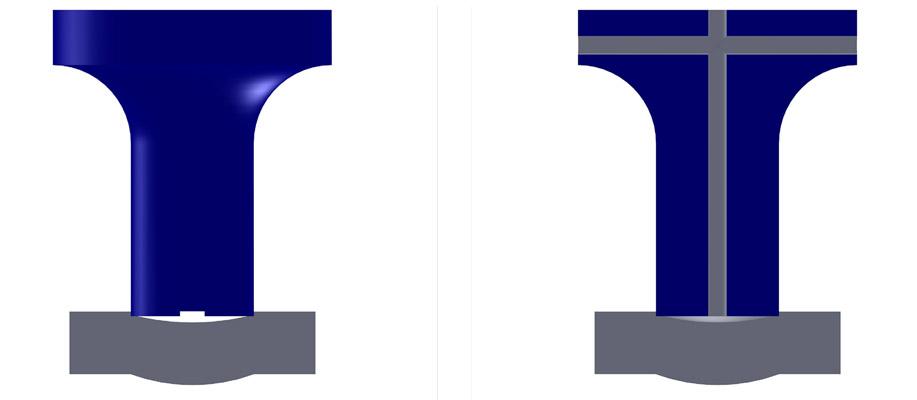
Figure 2
Slots cut into the punch face (on left) help break the vacuum created between it and the workpiece to help prevent slug pulling. Ejector pins mitigate slug pulling as well, but if they fail, the pins can be pulled out to create a ported punch, which itself can help reduce the suction.
Modern tool coatings help reduce heat in the punching process and, hence, can reduce the chance of galling. Some coatings work better for certain material grades and specific applications, so be sure to consult with your tooling supplier.
When punching a round hole, the hole naturally collapses slightly after the punch tip penetrates the sheet. A straight punch can rub against the workpiece material throughout the stroke. This rubbing creates more friction and heat, increasing the chances for galling. Back-taper can help here. If the punch has some back-taper, it makes only brief contact with hole sides after punching through (see Figure 4).
You might think tapering would work with the die as well, but this isn’t necessarily the case. When a die has a negative taper—a die with a smaller opening at the top than at the bottom—material tends to become trapped at the top of the die. This again creates friction, heat, and more chance for galling. In this case, you may want to consider alternative die geometries (such as the negative-positive geometry described previously) that allow room for debris to evacuate the die cavity.
Die clearance (that is, the space between the outside of the punch and inside of the die) plays a big role in galling prevention (see Figure 5). Tooling manufacturers publish die clearance charts, of course, and these can be a good starting point. But the best way to figure the right die clearance is to test a variety of die clearances with the material you’re working with and then determine which works best.
The optimal die clearance can depend on the speed of the punch. Though it may seem a little counterintuitive, a slower punch tends to require slightly more die clearance—just a few percentage points larger.
Older mechanical punch presses have long strokes of travel, with punches penetrating the material at high speed. Modern machines attain higher hit rates and greater productivity not by increasing the speed of the punch itself, but by using shorter stroke lengths so that the punch doesn’t travel as far. It penetrates the material and then rises up so that the tip is just barely over the top of the sheet. The machine performs more hits in less time, but the punch contacts the material at a slower speed. Make sure your die clearance takes this into account.
Yet another way to reduce the chance of galling is to ensure punches don’t overheat. Punches can heat up significantly after punching hundreds of holes in quick succession. In these cases, you may consider doubling up or even tripling up your tooling. You can punch a series of holes with one tool, then switch stations to another identical tool. This gives the other tool a chance to cool down.
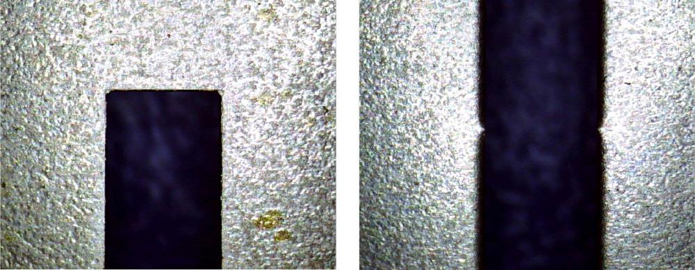
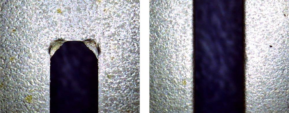
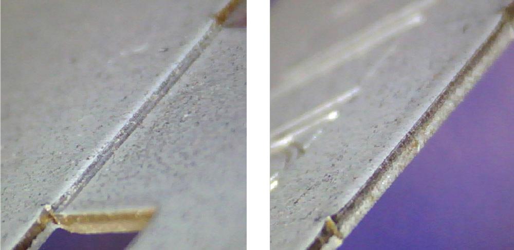
When the rectangular punch nibbles out a larger cut, the punch’s hard corner will carve hard overlap marks, which can create serious pinch points. Obround punches help eliminate these overlap marks (see Figures 6 and 7).
You can also use a pincher-roller wheel tool, which coins a groove before the punch tools penetrate the sheet. This requires a little extra cycle time on the punch press, but it’s well worth it if it eliminates an entire secondary operation like deburring.
5. Minimize Sheet Distortion
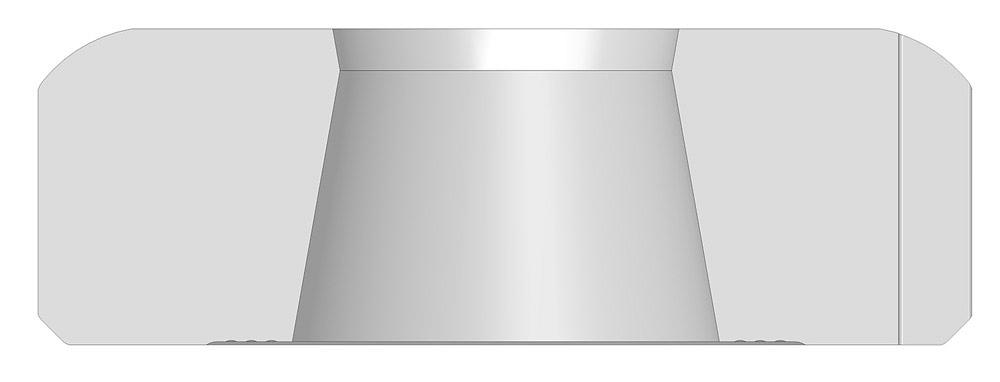
Figure 3
This negative-positive die geometry is designed to retain slugs once the punch ascends on the return stroke.
When the punch contacts the material, it naturally draws some of that material inward as it shears and penetrates the material. Minimizing sheet distortion boils down to mitigating this effect.
First, make sure the die clearance accounts for this material draw. Having too little clearance prevents the material from fracturing cleanly. This again produces galling and can distort the surrounding material.
Providing clamping pressure before punching starts helps not just with forming on the punch press, but actual punching as well. Some may choose to use a smaller stripper plate or have a smaller surface area on the die. This might reduce the overall pressure required to punch the material, but because you’re working over a smaller area, the pounds of pressure per square inch goes up. This in turn can help reduce the chance for the sheet to distort.
Note that this pressure can increase sheet marking, especially in soft aluminums and similar material. You are, after all, increasing pressure on the flat sheet, and some sheet metal grades are sensitive to this. Regardless, for most materials the marking usually is very minor, if it’s noticeable at all.
If you have a lot of holes to punch in a small area (and increasing the spacing between the holes isn’t an option), try programming so that the machine punches the holes randomly, rather than going back and forth in a linear “typewriter” pattern.
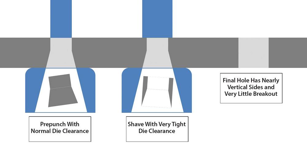
Hole shaving is yet another way to minimize sheet distortion. When hole shaving, the machine uses the same die size but two different punch sizes for the same hole. It punches first with the smaller punch (say, 9.8 mm in diameter) and then follows it with a larger “postpunch” (like with a 10-mm-diameter tool). This larger second punch “shaves off” the stressed area surrounding the hole perimeter (see Figure 8).
Programming microtabs (or “shaker tabs”) in nests is a common way to manage a lot of parts cut out of one large sheet. Sheets emerge from the machine, after which workers shake parts out of the nest for sorting.
his can work well, but this also can cause what’s known as “sheet shake,” when parts tabbed in a nest shake near the end of the program, when nearly the entire sheet is punched. Parts become unstable, which can cause positioning errors.
Here, changing the punching sequence can work well. The right sequence ensures that the web has enough strength throughout most of the punching cycle and that parts hang on by just their microtabs for the least amount of time possible.
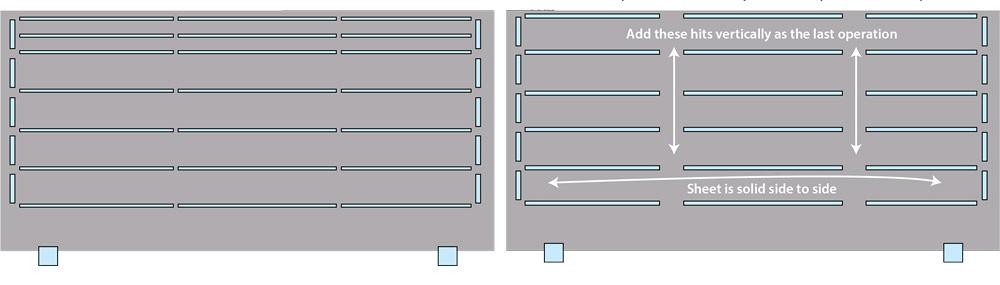
For instance, if you punched the nest in Figure 9 in “typewriter” fashion, back and forth, the parts in the first row would be shaking significantly by the end of the program. Alternatively, you could punch the nest so that the sheet remains solid from one side to the other for most of the program. Only at the very end would you add the extra hits to create the microtabs.
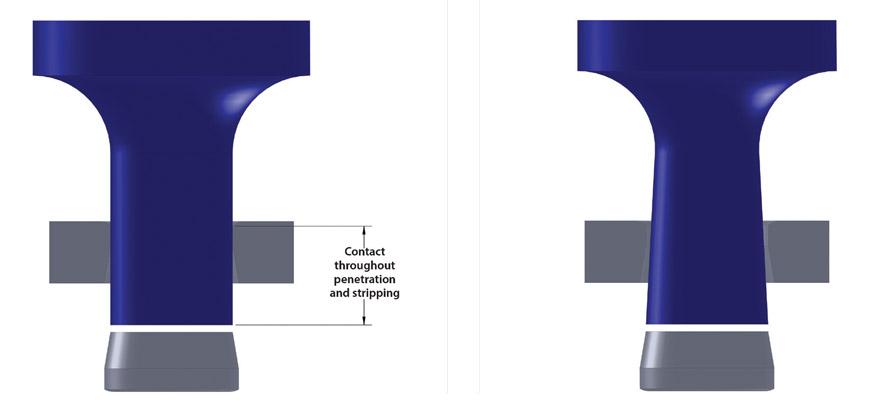
Figure 4
A punch with back-taper, as shown on the right, makes only brief contact with the sides of the hole, reducing the chance of galling.
You also can avoid sheet shake by punching a different type of tab. A half-shear tool created the tab in Figure 10. This tab is about 0.5 in. long, much larger and stronger than a typical microtab. But because the tool sheared partway through the material, workers still can take the parts out of the nest easily.
Many troubles in punching emerge not from a technical challenge, but instead from poor communication and recordkeeping. When you overcome any problem, be sure to document what was done and why.
For instance, say you have a louver tool, which has worked in the past flawlessly, yet now, for some reason, it isn’t. After some digging, you find that an operator changed the prepunch size to something slightly different than what it was. The prepunch may have worked for some jobs, but it’s not working for others.
Another common problem occurs when a shop gets an expedited order in, and the programmer rushes through nesting without assigning a specific tool for certain areas. He talks with the operator and shows him that the hit in this location, per the program, actually calls for the emboss tool, even though it isn’t identified in the program. So the operator inserts the emboss tool and all is well—until the next time the job comes up. The operator may not remember that the job needed the emboss tool, or the job may be sent to a different operator altogether. This problem wouldn’t have happened, of course, if the programmer had identified the tool for the program in the first place.
In all these cases and more, be sure to keep proper records, both of successes (when a punching strategy worked) and failures (when it didn’t).
These fundamentals are just the starting point, but they provide a solid foundation for future improvement. What about alternative tooling styles? Would retractable die stations benefit the operation? How about wheel tools, multitools, or tools that stamp identification marks directly onto parts? What if programming took tool life into account, “double backing” to apply nibbling hits in another direction, using all sides of the punch tool as equally as possible?
How effective any idea becomes depends, as always, on the application. Regardless, the key to improvement—in punching and anywhere else—can be found in one simple rule: Never stop asking questions.


The Fabricator is North America's leading magazine for the metal forming and fabricating industry. The magazine delivers the news, technical articles, and case histories that enable fabricators to do their jobs more efficiently. The Fabricator has served the industry since 1970.
start your free subscription
Easily access valuable industry resources now with full access to the digital edition of The Fabricator.

Easily access valuable industry resources now with full access to the digital edition of The Welder.

Easily access valuable industry resources now with full access to the digital edition of The Tube and Pipe Journal.

Easily access valuable industry resources now with full access to the digital edition of The Fabricator en Español.
In this episode of The Fabricator Podcast, Caleb Chamberlain, co-founder and CEO of OSH Cut, discusses his company’s...


