Contributing Writer
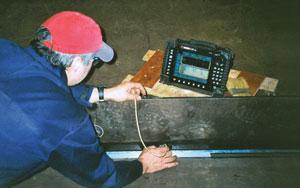 |
Ultrasonics is simple in principle, but complex in practice. A piezoelectric probe element is pulsed electrically and converts this pulse into a mechanical wave that travels into the component. This wave reflects from any discontinuity—a defect, back wall, or material change, for example—back to the probe and typically is read from an LCD screen. With digitization, these signals can be saved, displayed, and processed on a computer. Generally, these capabilities aren't exploited with simpler manual systems. Automation sometimes is used, though its cost and flexibility issues must be considered for each application.
One of the latest weld inspection methods being used is portable phased array ultrasonic inspection.1Ultrasonic phased arrays use multiple ultrasonic elements and electronic time delays to create beams by constructive and destructive interference. Phased array beams can be steered, scanned, swept, and focused electronically (see Figures 1 and 2).
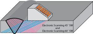 |
| Figure 1 These E-scans inspect a weld at two separate angles. |
Portable phased array units offer fast inspection speeds; full data storage; good imaging; multiple angle inspections; reproducible results; flexible setups; and small probe footprints. New software permits the use of two arrays at the same time on either side of the weld with multiple setups.
It's important to take care when considering a phased array inspection system. These systems generally are significantly more expensive than conventional ultrasonic systems, and they require training both to develop procedures and teach operators to ensure that reliable and consistent inspection results are achieved.
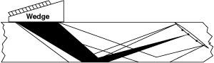 |
| Figure 2 S-scans of a weld can be sent from the front and the rear of the phased array. |
How It Works
Several features of portable phased array systems are important to know about before inspectors decide to try out this technology for their weld inspection applications.
Data Storage. Storing all scan data allows other displays, such as "top," side," and "end" views (C-, B- and D-scans, respectively). Several different combinations of displays are available, depending on requirements. Digital instruments can display the precise location of defects, such as defect distance from a weld centerline or depth.
Screen shots, rather than full waveforms, can be saved to help reduce data storage. Portable phased array units can be used to e-mail data files or transfer data and setups to and from other computers. Permanent data records aid long-term changes, as well as legal issues and reporting.
 |
| Figure 3 This S-scan shows a defect in the midwall. The B0 location is the root, and T1 is the cap. |
Imaging. Figure 3shows a typical swept-angle scan (S-scan) display of a crack in a plate.2The weld root and crown are identified by the designations B0 and T1; this defect lies between the two and is clearly a midwall defect, with both of the tips visible.
Small Footprints. Some welds have limited access because of flanges, other components, or geometry. Because of their small size, phased array units can offer extensive coverage of the weld, though not necessarily at optimum angles. A miniature array may be as small as a conventional transducer.
Speed. Using linear scanning along the weld, phased arrays typically can scan several times faster than manual raster scanning. This increase in productivity eventually should require fewer operators to perform inspections.
 |
| Figure 4 Multigroup scans using new software options can display two angles and one S-scan from one side. |
Training and Codes
Because phased array is a new technology, users will have to understand new concepts and issues that require training.
As with manual ultrasonics, phased arrays must follow code procedures for weld inspections. While none of the major code organizations has a phased array code yet, the ASME, the American Petroleum Institute (API), and the American Welding Society (AWS) accept phased arrays. ASME Code case 2235 specifically addresses automated phased array ultrasonic testing.
At this time performance demonstrations are being approached to establish the techniques and procedures for new technologies, and some examples have been established.3Generic phased array inspection procedures will be available soon, while specific phased array codes and code cases will be available in the future.
Michael Moles is industry manager for Olympus NDT, 48 Woerd Ave., Waltham, MA 02453, 781-419-3900, www.olympusndt.com.
Notes
1. R/D Tech, "Introduction to Phased Array Ultrasonic Technology—A Guideline," August 2004.
2. J. Mark Davis and Michael Moles, "Resolving Capabilities of Phased Array Sectorial Scans (S-Scans) on Diffracted Tip Signals," Insight, Vol. 48, No. 4 (2006), pp. 233-239.
3. R.K. Ginzel, E.A. Ginzel, J.M. Davis, S. Labb, and M.D.C. Moles, "Qualification of Portable Phased Arrays to ASME Section V," in proceedings from the American Society for Nondestructive Testing Fall Conference, sponsored by the American Society for Nondestructive Testing, Columbus, Ohio, Oct. 17-21, 2005.


The Welder, formerly known as Practical Welding Today, is a showcase of the real people who make the products we use and work with every day. This magazine has served the welding community in North America well for more than 20 years.
start your free subscription
Easily access valuable industry resources now with full access to the digital edition of The Fabricator.

Easily access valuable industry resources now with full access to the digital edition of The Welder.

Easily access valuable industry resources now with full access to the digital edition of The Tube and Pipe Journal.

Easily access valuable industry resources now with full access to the digital edition of The Fabricator en Español.
In this episode of The Fabricator Podcast, Caleb Chamberlain, co-founder and CEO of OSH Cut, discusses his company’s...