


President
 |
If the tooling is fine, you need to begin by dividing the process into three areas:
Then start eliminating the areas as potential causes of the problem.
One of the most neglected areas of a roll forming line is the machine face alignment. It doesn't matter how well the tooling is built and designed or how good the quality of the steel being roll formed is ... if the alignment is bad, the product will be bad.
 |
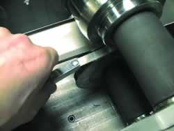
| Figure 1. A quick check with a straight edge on the roll form tooling can indicate a problem with machine face alignment. |
Many times a quick check with a straight edge on the tooling can tell you if there is a problem (see Figure 1). If you find a problem, you must remove the tooling and align the machine face.
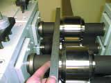
The first step in doing a machine face alignment is to check the shafts to make sure they are not loose or have bad bearings. If they are, you'll need to tighten or fix them (see Figure 2).
The next step is to remount the outboard stands and set the top shafts parallel to the bottom shafts. This can be done with calipers, a large micrometer, or machine face alignment rolls.
When all the top shafts are parallel with the bottom shafts, use a straight edge to align all the bottom shafts to each other, keeping them within 0.005 inch station to station.
 |
| Figure 2. The first step in doing a machine face alignment is to check the shafts to make sure they are not loose or have bad bearings. |
When all the bottom shafts are aligned to each other, use a smaller straight edge from the bottom shaft to the top shaft to align them to within 0.002 in.
The condition of the raw material also can affect the quality of the final product.
Material thickness variation may occur within the same coil from one end to the other. When it varies from one edge to the other edge, it is called crown. This is a smooth curve of consistent variation in thickness.
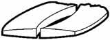 |
| Figure 3. When a coil with crown is slit into mults, the result is two wedge-shaped coils, one thicker than the other. |
Usually master mill coils are slit into narrower widths called mults. If the coil has crown, the result of the slitting is two wedge–shaped coils (see Figure 3). The one from the center of the master coil will be thicker than the one from the edge of the coil. Mults from a crowned coil also are cambered, which means one coil is longer on the left, while the other is longer on the right.
Mill coils with edge wave, then slit into narrow mults, show random camber in the outer strands-first in one direction and then the other. It is impossible to adjust for camber that varies throughout the mults. If the coil has continuous camber in only one direction, twist and sweep will be problems during the roll forming process.
 |
| Figure 4. Coil set and cross break may occur if support rolls aren't used at the exit of the straightener, leveller, or feed device. |
Coil set and cross break may occur if support rolls of the proper configuration are not used at the exit of a material straightener, leveler, or entering feed device (see Figure 4). Without the support rolls, the strip breaks harder over the entrance rolls or exit rolls, creating these conditions.
Another dimensional variation is crossbow. This condition may occur during the coiling process at the mill or slitter and is caused by an incorrect slitter setup. With crossbow, the top surface of the material, edge to edge, is not equal in length to the bottom surface. The shorter surface is inside of the radius.
Forcing material with coil set and crossbow to lie flat will cause oil canning, which means the center of the strip will be longer than the edges. Forcing the material in the opposite direction will cause edge wave.
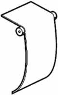
The third area to examine is the tooling setup.
You should document setups so they can be repeated as closely as possible each time the tooling is put onto the roll forming machine. One way to do this is to record the flange or hub settings between the rolls with the material in the tooling.
 |
| Figure 5. An inspection mirror and flashlight can help you look for gaps or see if the tooling is down, touching the material. |
Keep the roll form machine and tooling clean and free of any grit or material that may change tooling alignment from top to bottom. Wipe the spacers, shafts, and tooling clean before installation.
The roll form tooling should be producing the desired cross section before the straightener is mounted. If the cross section is not to print, remove the straightener and adjust it before remounting.
Roll form tooling that is set up properly will produce a symmetrically shaped part that does not twist.
 |
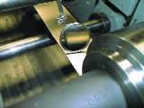
| Figure 6. An optical comparator compares the actual roll form tooling to the original design. |
Following are some helpful hints that can be used during the troubleshooting of roll form tooling:
 |
| Figure 7. Wire gauges passed through a roll form tooling pass can indicate loose or tight spots. |


The Fabricator is North America's leading magazine for the metal forming and fabricating industry. The magazine delivers the news, technical articles, and case histories that enable fabricators to do their jobs more efficiently. The Fabricator has served the industry since 1970.
start your free subscription
Easily access valuable industry resources now with full access to the digital edition of The Fabricator.

Easily access valuable industry resources now with full access to the digital edition of The Welder.

Easily access valuable industry resources now with full access to the digital edition of The Tube and Pipe Journal.

Easily access valuable industry resources now with full access to the digital edition of The Fabricator en Español.
In this episode of The Fabricator Podcast, Caleb Chamberlain, co-founder and CEO of OSH Cut, discusses his company’s...


