


End distortion on roll formed parts
Investigating causes and cures
 |
End distortion is a birthmark caused by the roll forming process. Roll forming—a process in which a flat strip is bent continuously and progressively in the transverse direction by tandem sets of roll tooling—induces residual stresses in compression on the inner surface, residual stresses in tension on the outer surface, and residual moments in the cross section. Cutting the formed part releases the residual stresses and moments, which can result in distortion at both ends of the part. Understanding the causes of end distortion can help fabricators prevent and correct these types of defects in roll formed parts.
Keep in mind that roll forming has three forming regions. The first region is the noncontact forming (air bending) region. The second region is the contact forming (tool bending) region that ends at the central line of the rolls. The third region is the springback region that begins as the section exits the central line of the rolls. The profile transition region comprises both the noncontact forming region and the contact forming region.
The stresses and moments are products of not only the forces exerted on the strip, but also the distances between the forming regions.
 |  |
| Figure 1 The roll forming process results in surface residual tension and residual moment. As the term implies, the residual moment is a force that remains in the roll formed profile. Cutting the product releases this force and can cause distortion. | Figure 2 The leading ends of these three products show three possible outcomes: toed in, flared out, and no distortion. |
Sources of Distortion
The bending moment is the result of two forces. The top roll exerts one of these forces by pushing down on the channel's center. The bottom roll exerts the other force, pushing up on the channel's flanges. Cubes are helpful in illustrating the processes that result in end distortion (see Figure 1). The first cube shows the bending moment. On the front side of the cube, the bending moment is clockwise. On the back side of the cube, the bending moment is counterclockwise. The bending moment twists the channel flanges up in both the air bending region and the contact forming region and settles to the residual moment after the material comes out of the forming rolls. The second cube shows the residual moment. On the front side of the cube, the residual moment is counterclockwise. On the back side of the cube, the residual moment is clockwise.
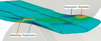
On the outer surface of the channel, stress starts by causing tension at the air bending region, then changes to compression in the contact forming region, and settles to the residual tension after coming out of the forming rolls. On the inner surface of the channel, stress starts as compression at the air bending region, changes to tension in the contact forming region, and settles to the residual compression after coming out of the forming rolls.
Releasing these forces results in a leading end as shown in Figure 2:
- If the action of surface residual stress release and the action of residual moment release are the same amount, the leading end is straight.
- If the action of surface residual stress release is greater than the action of residual moment release, the leading end is flared out.
- If the action of surface residual stress release is less than the action of residual moment release, the leading end is toed in.
Other Causes for Distortion
 |  |
| Figure 3 Prenotched material doesn't go through the rolls as smoothly as material that has continuous channel flanges. The back edges of the notches can hit the roll tooling. | Figure 4 Both ends are flared by the cutoff process—in this case, a slug-type cutoff die with a pushing-out design that cuts in the vertical direction. |
Prenotched material also provides a challenge for producing good parts with no distortion.
In prenotched material, the notches separate the channel flanges into segments. The back edges of the notches can hit the rolls (see Figure 3). The higher the forming speed, the harder the back edges hit. This impact bends up the back edge of the notch and can cause it to toe in.
During the coil threading process, the two corners at the leading end of the coil act similarly to the back edge of a notch: The front two corners of the coil hit the rolls, the two corners bend up, and the leading end of the channel toes in.
Another potential cause of distortion is the cutoff process. A cutoff die can cause distortion at both the leading and trailing ends of a roll formed profile (see Figure 4).
Troubleshooting
- A downhill design minimizes end distortion. Although the word downhill implies that each pass is lower than the preceding pass, this isn't the case. In a downhill design, the midpoint of the metal profile is at the same height in every forming pass. A downhill design has less longitudinal elongation and less forming moment than a conventional uphill design (in which the midpoint of the metal rises progressively). A downhill design minimizes end distortion at the design stage.
- A long profile transition region—the region that comprises the noncontact and contact forming regions—has less angle increment per length, less forming moment, and less end distortion than a short profile transition region. A large bottom roll has a longer profile transition region and less end distortion than a small bottom roll.
Figure 5
Using side rolls can help to prevent end distortion. When forming prenotched materials, side rolls prevent the notches from hitting the rolls in the forming passes. They should be set up to form 50 percent to 100 percent of the forming angle of the next forming pass.Figure 6
Post-treatments include counterforming, straightening, and a combination of counterforming and straightening.
- A pair of side rolls mounted before the forming pass (Figure 5) is a common method for preventing end distortion. These side rolls increase the profile transition distance, reduce the angle increment per length, and reduce the forming moment. Side rolls reduce the surface stresses in the profile transition region (forming zone) and therefore reduce the residual moment and residual surface stress and minimize end distortion. Setting up the side rolls to form about 50 percent of the forming angle for the following forming pass helps to reduce end distortion.
- Side rolls are necessary for forming a prenotched product. They should be set up to form more than 50 percent of the forming angle for the following forming pass. For very thin and very soft metal, the side rolls may form 80 percent or even 100 percent of the forming angle for the following forming pass. This eliminates the toeing in of the back edge of the notch caused from the impact force (Figure 3).
- Consider additional forming passes, especially for prenotched products.
- Figure 6illustrates three post-treatments. The C method in Figure 6 is a counterforming method in which all residual moments and stresses are balanced.
- The S method in Figure 6 is a straightening method in which the alternating bending flattens out the ends and eliminates distortion.
- The CS method in Figure 6 is a combination of the counterforming method and the straightening method. It balances the residual moment and the surface stresses and flattens out the ends and eliminates distortion.
- Distortion caused by a pushing-out-style slug cutoff die with a vertical cutting motion (see Figure 4) is reduced or eliminated by changing to a slugless cutoff die with a 45-degree cutting direction.
Hanhui Li is senior engineer with Worthington Armstrong Venture (WAVE), 9 Old Lincoln Highway, Suite 200, Malvern, PA 19355, 610-722-1232, fax 610-722-1246, hanhui_li@armstrong.com.
References:
Kenzo Kato, "Cold roll-forming," Japanese Industry News, 1971 (in Japanese).
Manabu Kiuchi, "Recent Development of Roll-Forming In Japan" Int. J. Mach. Tools Manufacture, Vol. 29, No.1 (1989), pp. 63-77.
Hanhui Li and Fred J. Gradous, "Designing Roll Forming Tooling Flanges" The FABRICATOR®, April 2000, pp. 30-32.
Hanhui Li, "Developing a Design for Cold Roll Forming" The FABRICATOR, April 1998, pp. 28-37.
Takashi Jimma and Hideo Morimoto, "Grid Stress Analysis of Cold Roll Forming Process of Channel" Journal of the JSTP, Vol. 26, No. 288 (1985) (in Japanese).
Chuck Summerhill, "Minimizing Production Problems in Roll-Form Tooling Design" Roll-Kraft Inc., 2002.
Hiroshi Ona et al., "Distortion Near Cut-off Edges on Channel, Hat-channel and C-channel Sections: Research on the High Accuracy Cold Roll Forming Process VI" Plasticity & Manufacture, Vol. 24, No. 268 (1983) (in Japanese)
About the Author
About the Publication
subscribe now

The Fabricator is North America's leading magazine for the metal forming and fabricating industry. The magazine delivers the news, technical articles, and case histories that enable fabricators to do their jobs more efficiently. The Fabricator has served the industry since 1970.
start your free subscription- Stay connected from anywhere

Easily access valuable industry resources now with full access to the digital edition of The Fabricator.

Easily access valuable industry resources now with full access to the digital edition of The Welder.

Easily access valuable industry resources now with full access to the digital edition of The Tube and Pipe Journal.

Easily access valuable industry resources now with full access to the digital edition of The Fabricator en Español.
- Podcasting

In this episode of The Fabricator Podcast, Caleb Chamberlain, co-founder and CEO of OSH Cut, discusses his company’s...


