


Senior Editor
Roll forming specialist David Rostocil doesn’t believe in “black magic.” People say that the best roll formers have to gain a “feel” for the process, but Rostocil doesn’t think of it that way.
“You have to take the black art out of it,” he said. “We don’t want to just have a feel for it. We want to gauge the rolls. We want to know what we have.”
That’s the idea behind Rostocil’s forming seminars. As senior technical performance specialist at Roll-Kraft, he has held numerous events, organized by his Ohio-based employer as well as by organizations like the Fabricators & Manufacturers Association International®.
A 40-year industry veteran, Rostocil spent 20 of those years at a custom roll form facility. As he tells the story, he didn’t learn the craft by gaining a “feel” for the machine. He learned by listening to his mentors, the “old engineers” who taught him the ropes and talked about specifics, like what to do and what to avoid to operate an efficient rolling mill, setup after setup.
“Sometimes the people who run these machines are seen as not very technical,” Rostocil said. “Sometimes they don’t have drawings. But how can operators know where to go if they don’t have drawings? They may need to be trained or attend a seminar, but it doesn’t take long with the proper training. They learn very fast.”
In effect, the print gives the operator the destination. It identifies the dimensions, material grade, material thickness, radii, and the key control passes. Every set of tooling usually has at least two key control passes, and depending on the severity of the formed section, the operator could have multiple passes that need the proper amount of overform in each to accommodate for material springback.
The setup chart (see Figure 1) is the operator’s vehicle that gets him to the destination. Setup charts should include not only the basics—number of passes, rolls and shim specs, flange gauging points, as well as inboard and outboard spacer dimensions—but also operator notes describing setup intricacies as well as lessons learned from previous runs.
For instance, say a job requires side-roll stands. Before the first pass, the setup sheet might include an explanation, “Mount side-roll stand before the first pass; use edging rolls to keep return legs even.” Additional notes might include something like, “Excessive pressure on passes 9-12 will cause leg heights to become short.”
As Rostocil explained, it’s difficult to give too much information on the setup chart. The more complete the chart is, the smoother an operator’s roll forming road trip will be.
If the print is the destination, and the setup chart represents the vehicle, a documented standard operating procedure is the road map.
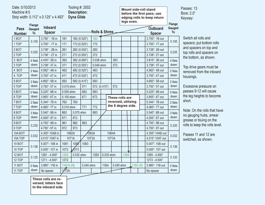
Figure 1
A setup chart should not just describe the basics, like number of passes and roll and shim specs, but also contain notes describing setup intricacies as well as lessons learned from previous runs.
The procedure should involve setting the rolls on the machine, gauging the rolls to ensure the distance between them matches the thickness specified on the setup chart, and checking the side clearances and roll alignment without material in the rolls.
(To troubleshoot one pass that is out of alignment, a technician should pull the tooling off and gauge it on a surface plate, Rostocil said. The machine itself may be perfectly aligned; the problem may lie with the tooling. Measuring both the machine and the tooling can help pinpoint the cause of the misalignment. For more on alignment, see the Roll Forming Maintenance Tips sidebar.)
Check the roll spacing. The operator inspects all the rolls to make sure the space between the upper and lower tools mirrors what’s shown on the part print. To do this, the operator places a piece of white paper behind a roll set, then places a mirror in front of the rolls and tilts it 45 degrees. This gives him a good view of the space between the rolls, which should match the part profile on the print (see Figure 2). If it does not, the operator needs to adjust the tooling accordingly, by using shims to align the rolls.
Alternatively, an operator can just crack the nut on the shaft and insert a horseshoe, or split, shim without taking the tooling off the machine. If the operator does this, he will need to double-check the alignment using a feeler gauge. “But watch out,” Rostocil said. “Those horseshoe shims can work their way out at high speeds, and you can lose your alignment anyhow.”
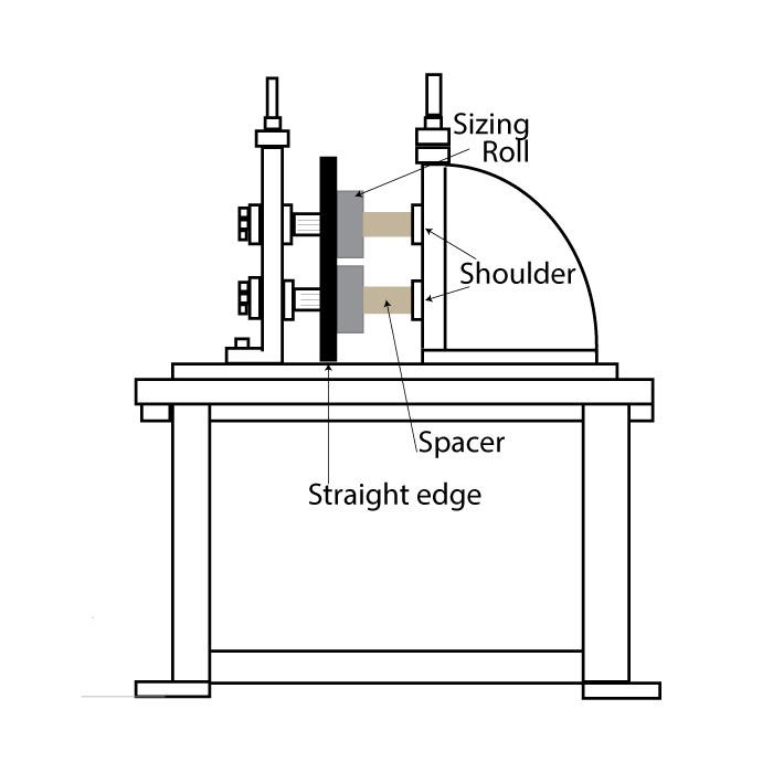
Check the entry table height. Next comes what Rostocil said is a step many operators forget: using a straight edge to make sure the entry table is at the proper height, aligned with the entry rolls (see Figure 3). “Many assume the entry table is always going to be perpendicular and parallel going into the entry rolls. If the table is not perfectly in line with the tooling, the material will skew and twist at the end of the machine. Many times operators focus on the rolls near the end, when the problem really starts at the entry table.”
Set the side-pass stand height and center the side rolls. Similarly, if the job’s tooling set uses side rolls—which are mounted on a vertical axis and located between passes to help maintain the profile shape—an operator should check the stand height with a dial indicator.
To center the side rolls, the operator can use a straight edge to measure from the flat surface on the roll form machine, from the pass just before or after the side-pass stand. The distance on both sides of the roll should be the same.
Measure the material thickness. To find the most efficient route, an operator needs to know exactly where he’s starting out, and this is where the material comes into play. An operator should measure the actual thickness of the coil material that will be formed. If the setup chart and print says 16-gauge material, an operator may just set up the material for 0.060 in. Yet the actual material may be a little thicker or thinner.
“You need to make sure the tooling will accept the thickness of material that’s coming into the machine,” Rostocil said.
“If you don’t know exactly what material thickness is being formed into the machine, how do you know where you’re going?”
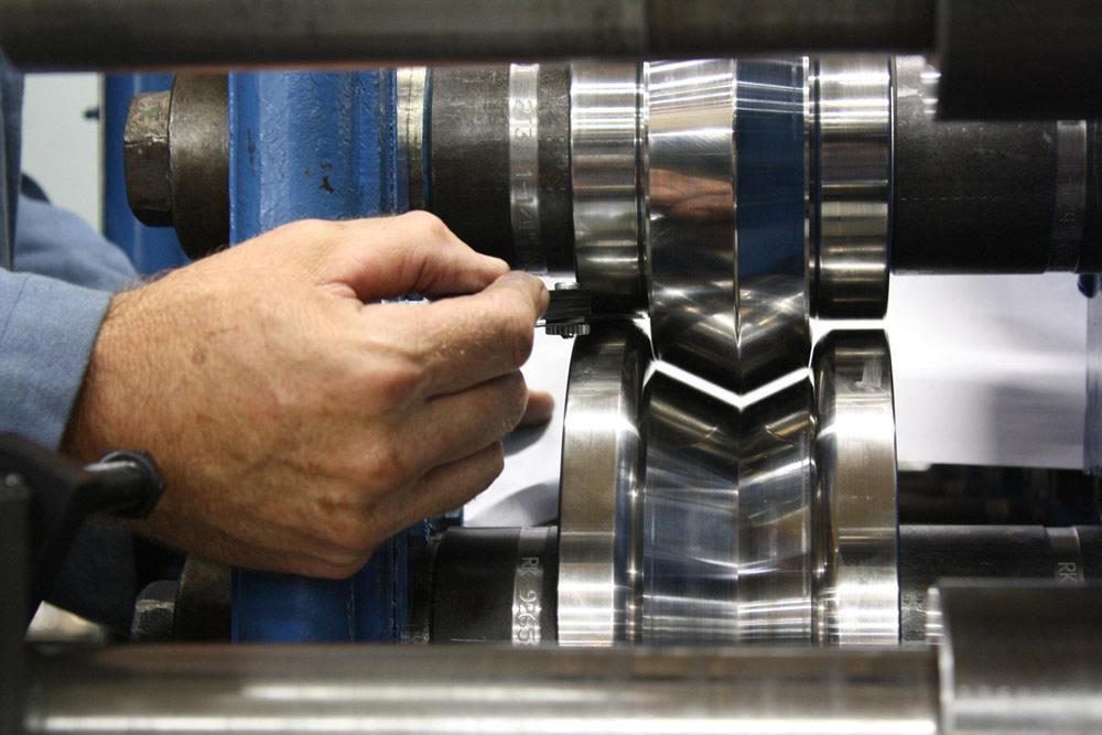
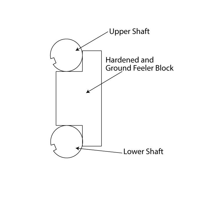
When setting the rolls with the material, the operator should make sure the feeler gauge has a snug fit between the upper and lower shafts (see Figure 4). “It should be a little snug,” Rostocil said, “and it should feel the same on both the inboard and outboard sides of the machine. You need to make sure you have the proper clearances for the material and for the radii being formed, and make sure everything is set.”
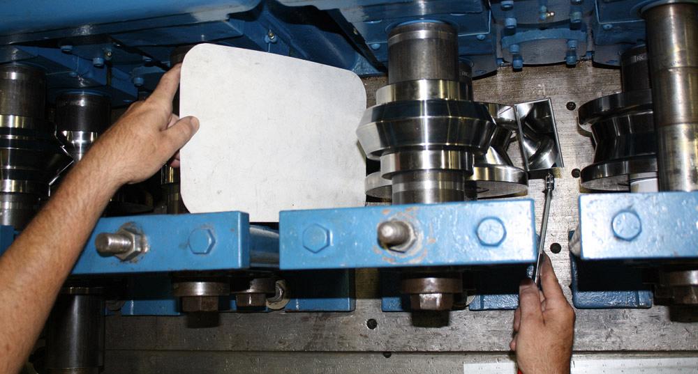
Figure 2
Placing a white piece of paper behind the tooling, an operator holds a mirror at a 45-degree angle to view the profile space between the tooling. That space should match what’s shown on the print. If it does not, the operator needs to adjust the tooling accordingly by using shims to align the rolls.
Feed, jog, and adjust. Even on a brand-new machine, the roll stands’ gearbox components (bearings, housing and adjustment nuts, etc.) shift upward once material feeds into the rolls. To compensate for the bearing slop and other movements, an operator inserts a feeler gauge between the top and bottom rolls to reset the roll position to the proper gap. Where to put the feeler gauge depends on the tool profile, but usually the operator places the gauge to ensure the roll remains as parallel as possible on the shaft.
Still, the worst thing an operator can do here is to adjust quickly down “hard” on the gauge until the material feed slows. “This is where you get the squeeze-out,” Rostocil said. “Squeeze-out” occurs when the top and bottom rolls, gapped too close together, squeeze and distort the material, causing twist, bow, camber, and other issues during production. Instead, operators jog the material 1 or 2 in. to allow material to seat in the rolls, then readjust and jog again as necessary. Then it’s on to the next roll.
“For newbies, this can take quite a while, maybe up to 20 minutes per stand,” said Rostocil. “But once you get accustomed to it, you can adjust the roll fairly quickly.”
Run test pieces, measure, then add the straightener and cutoff. The number and length of test pieces depend on the job, but regardless of the application, operators need to measure the profile, compare it to the print, make the appropriate adjustments, then document them in the setup chart.
Once the piece meets specifications, operators then can add the straightener as well as a cutoff system. As Rostocil explained, the straightener is there to account for material and process variation, and it shouldn’t need to straighten the section coming off the mill significantly. In fact, ideally, the section should emerge from the mill as straight as possible. “Otherwise, you might have trouble running a straight profile during production.”
Material quality matters in any metal forming process, and this of course includes roll forming. But as Rostocil explained, it’s not the operator’s job to complain about the material. “It’s his job to help document the process and make it work.”
This includes documenting material thickness variation, the adjustments those variations require, and even the time those adjustments take. It’s one reason that measuring material thickness periodically throughout the run is so important. He can then share that documentation with supervisors and purchasing personnel.
“I worked at a roll form company for 20 years, and spending a few cents more for better material gave us more than twice the production,” Rostocil said.
Similar thinking goes for tooling choices and the number of stations (passes) on a mill. A roll form operation may try to “make it work” with fewer-than-optimal roll stands, sometimes adding some side rolls to ensure proper forming. All this adds to the setup time, though, and can make the process unpredictable. Documenting all this may help make the case for more roll stations and a better tooling setup.
If the operator records where variation occurs—from poor material or a suboptimal tooling setup—and includes all the subsequent adjustments that variation causes, he ultimately can help the company make better decisions. And those decisions should be based not on some special black magic or a feel for the process, but actual process data that shows what’s happening at the roll forming mill—and why.
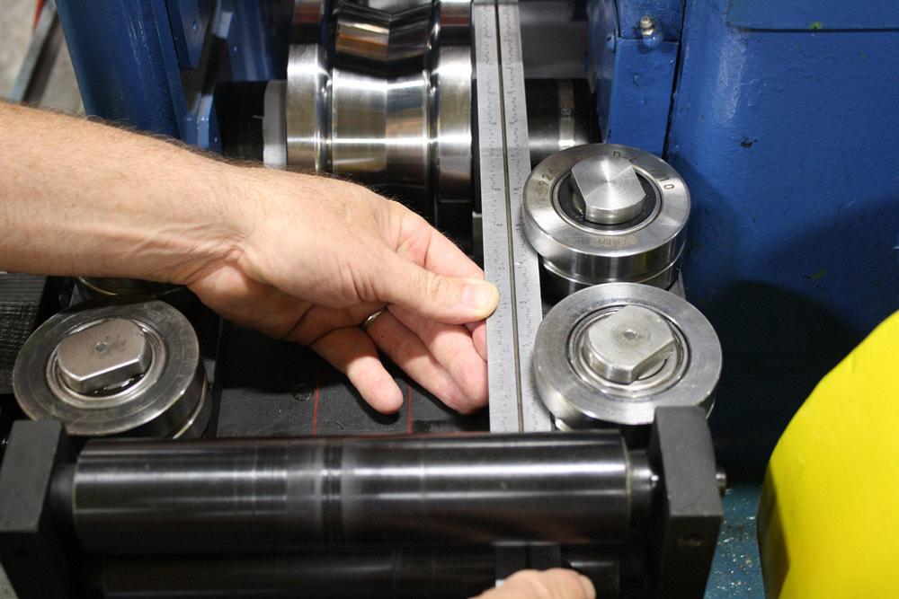
Figure 3
An operator uses a straight edge to ensure the entry table is at the proper height.
Images courtesy of Roll-Kraft, 888-953-9400, www.roll-kraft.com.
To ensure the machine stays in good working order, technicians should perform a comprehensive integrity check and alignment. If an operator performs basic preventive maintenance tasks, such as applying grease and tightening bearing nuts, technicians shouldn’t have to check alignment very often, sometimes just once a year. But as always, maintenance frequency depends on the application.
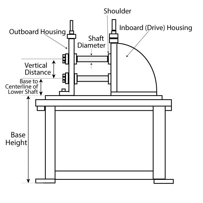
Roll form machine maintenance includes ensuring bearings on the stands are in good working order, are preloaded properly, and give the proper “float” to accept the shafts. A tech may also inspect the inside diameter of the shafts using a telescoping or boring gauge and inspect the outside diameter with a micrometer to ensure it’s within tolerance (usually within -0.001 in. per 1 in. of the shaft OD).
For drive stands, where the inboard stand incorporates the transmission, the technician will inspect the bearing blocks and tighten and adjust by machining them or using shims to ensure the assembly has a tight fit and the slide can move the top shaft up and down with precision.
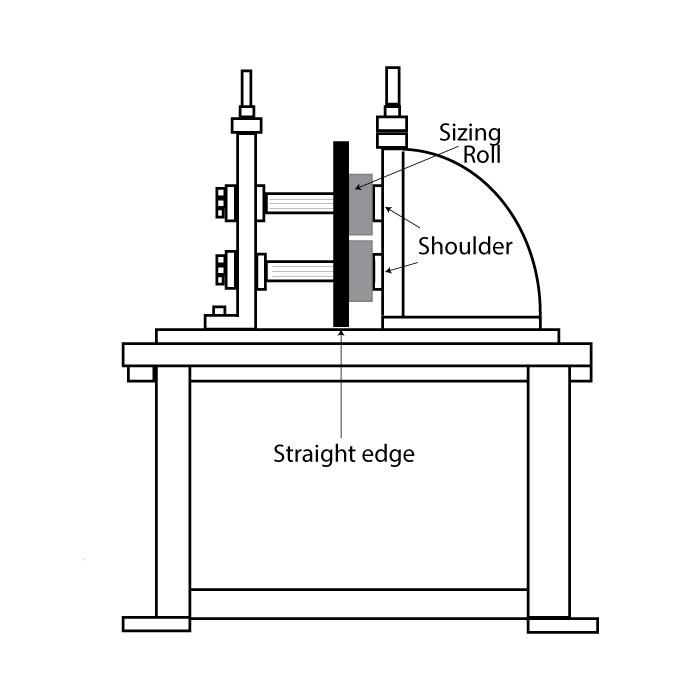
The top shoulder also needs to be lined up with the bottom shoulder, often by using sizing rolls of equal width as a “fixture,” slid along the shaft against the top and bottom shoulders. This gives the tech more points of contact when using a straight edge.
Once the tools and spacers are on the machine, the technician can place a straight edge on both sides of the rolls to ensure the top and bottom shafts are parallel. If spacers are too narrow for a straight edge, a tech may insert a drill rod against the rolls to check for parallelism.
A technician also checks for shaft parallelism by placing a feeler block between the shafts, being sure alignment is the same on both the inboard and outboard sides.


The Fabricator is North America's leading magazine for the metal forming and fabricating industry. The magazine delivers the news, technical articles, and case histories that enable fabricators to do their jobs more efficiently. The Fabricator has served the industry since 1970.
start your free subscription
Easily access valuable industry resources now with full access to the digital edition of The Fabricator.

Easily access valuable industry resources now with full access to the digital edition of The Welder.

Easily access valuable industry resources now with full access to the digital edition of The Tube and Pipe Journal.

Easily access valuable industry resources now with full access to the digital edition of The Fabricator en Español.
In this episode of The Fabricator Podcast, Caleb Chamberlain, co-founder and CEO of OSH Cut, discusses his company’s...


