


Contributing Editor
 |
In roll forming, nonstop punching and shear systems typically deliver the highest output. Although these systems traditionally have employed open-loop control methods, closed-loop (also called servo-based) systems can yield high line speeds while helping to decrease downtime and reduce scrap.
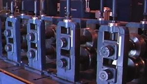
Coil-fed roll forming systems require a measuring system to size the parts and activate the cutoff press at the exit end of the machine (see lead image).
Certainly, in some situations, it is better to index the material through punching or shear presses; however, when conditions allow, running the material continuously typically leads to higher production rates.
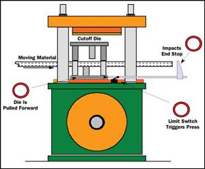 |
| Figure 1 In the simplest type of open-loop die acceleration system, the material itself engages the die and pushes it forward using a gauge bar. |
An open-loop system uses a timed mechanical method to accelerate the die with the material to make the cut. The term open-loop refers to the system's lack of a means of providing location feedback for the cutting tool, and so it can't make the needed speed adjustments based on that feedback.
The performance of an open-loop system is greatly affected by the repeatability of the press, the consistency of the material speed, and the setup of the machine and control system. While an open-loop system can achieve high speeds and good accuracy, its performance depends heavily on well-trained, experienced operators and attentive maintenance staff to monitor, maintain, and adjust the system.
In an open-loop die accelerator system, the die is accelerated in four principal ways:
Engaging Material—Gauge Bar. In the simplest form of die acceleration, the material engages the die using a gauge bar and pushes it forward (see Figure 1).
The gauge bar has an end stop located exactly one part length away from the die. The leading edge of the roll formed material hits the target, pushing the gauge bar forward and the die forward along with it. The die then trips a limit switch, which activates the cutoff press. The cutoff occurs while the material is pulling the die forward. When the cut part falls away, springs or an air cylinder pulls the die back to its home position.
This cutting method is very accurate, but part lengths are limited by the length of the gauge bar—for instance, a 30-foot part requires a 30-ft. gauge bar. Line speeds are limited because of stress and buckling at the cut point; the higher the speed, the greater the force of compression, and the greater the chance of damaging the system, the part, or both. Also, changing from one part length to another can generate excessive scrap.
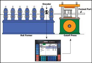 |
| Figure 2 A second method of accelerating the die by engaging it with the material is used on machines with electrical measuring systems. An encoder provides a set number of pulses per one revolution of a wheel. Counting pulses, the controller uses the wheel's circumference to calculate the length the material travels and then signals the press to cut. |
Engaging Material—Electrical Measuring. A second method of accelerating the die by engaging it with the material is with electrical measuring systems such as flag switches. On these systems, a flag or limit switch is placed exactly one part length downstream from the cutting tool. When the leading edge of the part makes contact with the flag switch, the press activates and the die engages the material. The material pushes the die forward as the remainder of the cycle is completed. Once the cut is complete, the die retracts from the material and returns to its home position.
A more sophisticated electronic length control method uses an encoder in combination with a controller (see Figure 2). An encoder provides a set number of pulses per one revolution of a wheel of a specified circumference. Counting pulses, the controller uses the wheel's circumference to calculate the length the material travels. When the length traveled matches the length programmed into the controller, the controller signals the press to activate the cutting cycle.
An encoder- and controller-based open-loop system allows flexibility by supporting multiple lengths without incurring scrap or downtime. Also, consecutive lengths can vary from one part to the next without the need for an operator to stop or reconfigure.
In both engaging material methods, the impact on the material is abrupt, so their use is limited to lines with very low speeds and materials with very stiff profiles. At higher speeds (relative to the part's material and complexity), the end of the part can be damaged, or bowing can occur. Neither method protects the part any more than the other; it simply shifts the contact point from one place on the part to another.
Mechanical Kicker. In mechanical kicker acceleration, a ramp is situated at a fixed position on the press. As the press closes, a roller on the die meets the ramp and pushes the die forward until it makes its cut. A spring or air cylinder then returns the die to the home position.
Kickers are simple and relatively inexpensive to install. The angle of the ramp, however, must be adjusted carefully so the die matches the material speed precisely. Even a slight difference in speed can damage the part, the die, or both, as well as cause part length inaccuracies.
Die Boost Cylinder. Boost cylinders are pneumatic or hydraulic cylinders that are activated just before or at the same time as each cut to push the die forward and then return it to its home position after the cut. For part length to remain consistent, the die must return to the precise home position before the next cut. Boost cylinders can be used to lessen the die's impact on the material.
This system is inexpensive, easy to implement, and effective as a die accelerator. Boost rate is an important but difficult variable with this method—a particular boost pressure and timing may work well only for a narrow range of material speeds. The machine control can provide an analog signal that is proportional to the current machine speed.
 |
| Figure 3 A closed-loop die accelerator system uses a positioning device that precisely controls the location of the die across the entire stroke length of the press. When a cut is made, the positioning device moves the die directly over the cut point, keeping it at the same speed as the material throughout the entire press cycle. |
While an open-loop system can achieve high speeds and solid accuracy, its results depend significantly on the training and experience of the operator and maintenance staff. A closed-loop system, however, can produce good results consistently, with minimal attention and maintenance.
A closed-loop die accelerator system uses a positioning device that controls the location of the die across the entire stroke length of the press. When a cut is made, the positioning device moves the die directly over the cut point, keeping it traveling at the same speed as the material and tracking throughout the entire press cycle (see Figure 3).
Because the die and the material are traveling at the same velocity, the cut is made at virtually zero speed—as if it were a standing cut—resulting in a clean cut without strain on the material or on the die. This eliminates collision between the material and the die and allows increases in line speed without part damage, improving part quality and extending the life of the cutoff die. Once the cut is performed, the positioning system returns the die to its home position to await the next target.
A closed-loop die accelerator's main advantage is that it can make adjustments throughout the press cycle on the fly through its feedback systems. It can achieve consistency and accuracy in a variety of conditions without continuous oversight. Length control is accurate without speed constraints and with almost no setup time for length changes. Parts lengths remain accurate over a range of machine conditions.
Initial equipment cost is high for closed-loop systems because of the required precision die-positioning system. However, increased line speeds, scrap savings, and reduced downtime can help justify the investment.
The cycle rate of any roll forming machine's cutoff press limits the minimum part length that can be run at a given line speed. A closed-loop die accelerator actually limits this speed further and lengthens the cycle rate of the cutoff operation. Before a cut, the die must be accelerated to line speed; after the cut, the die must be decelerated to a stop, accelerated in the reverse direction, and decelerated as it approaches the home position.
With so much die movement, shorter parts must be run at lower line speeds. However, because a closed-loop die accelerator adapts to line speed changes, the machine can be slowed down for short lengths and immediately sped up for longer lengths with no downtime or deterioration of accuracy.
Linear motion is essential in a closed-loop die accelerator system, and in most systems of this type, the linear actuator is the key element that creates the linear motion to move a die or press. Four principal types of closed-loop die accelerator systems are available:
 |
| Figure 4 Many closed-loop die accelerator systems today use rotary servomotors with rotary-to-linear converters. With a rotary servomotor, a linear actuator converts the rotary motion of the motor into the linear motion of the die and positions the die in line with the material flow. |
Rotary Electric Motor With Rotary-to-Linear Conversion. Most closed-loop die accelerator systems today use rotary servomotors with rotary-to-linear converters (seeFigure 4).
With a rotary servomotor, a linear actuator must be used to convert the rotary motion of the motor into the linear motion of the die. The linear actuator positions the die in line with the material flow. There are several types of linear actuators in use, including:
Feedback for the die position usually is taken from the motor shaft. Any errors in the linear actuator are outside the loop and cannot be compensated for.
The ball screw is one of the more precise types of linear actuator. The ball nut moves a precise distance for each rotation of the screw, with low backlash. Because of the pitch of the ball screw, in most cases the servomotor can be directly connected to it without the need for gear reduction.
The ball screw is suitable for applications with lightweight dies and low speeds that require highly accurate parts. It should not be used for speeds of more than 300 feet per minute (FPM) because of a whipping action of the screw at high speeds.
Rack and pinions have been used as linear actuators in many applications with high speed and high die weights. The rack is located parallel to the material flow and acts as the die pusher. The contact point between the rack and the pinion gear is critical for this application and can be a point of wear and breakage.
Usually the pinion gear cannot be connected directly to the servomotor; a gear reducer with low backlash typically is required so that the motor can run at near full speed to provide the necessary torque and to match the system inertia.
With a timing belt, two pulleys are located in line with the material flow. A bracket is attached to the belt and coupled to the die, and a servomotor is coupled to one of the pulleys through a gear reducer. This system achieves high line speeds with moderate die weights.
For accuracy, timing belts must be sized accurately. They are like large rubber bands and must be within the specified working speed and force to avoid being stretched.
Brushless direct-current (DC) servomotors with computerized drive systems offer high performance at relatively low cost. They require little maintenance and are easy to tune.
Hydraulic Cylinder With Servo Valve. The hydraulic system is one of the oldest types of closed-loop die accelerators. This system is suitable for heavy dies and high line speeds, but fluid contamination is always a concern, and tuning the system often requires a skilled technician.
Pure Rotary. Rather than using a rotary-to-linear conversion device, the rotary electric motor directly drives a rotary shear for cutoff. Especially suitable for cut-to-length applications, the rotary shear allows for higher speed because the shear no longer is required to reverse direction, allowing for lower cycle times.
Linear Motors. A linear motor is essentially a rotary motor that has had its rotor and stator split and pressed flat. Unlike the other three principal die accelerator methods, a linear motor creates linear motion directly, without the need of a device to convert the rotary or hydraulic fluid motion. The rotor and stator are placed closely together in parallel, with one attached to the machine in a fixed position and the other attached to the die. Electrical currents in windings cause the two plates to attract and repel each other in a controlled fashion that moves the die in the direction of the material flow.
Not only do linear motors eliminate the need for a linear actuator, but with their very low inertias, high accelerations are possible. There is also no backlash with a linear motor and no moving parts to maintain, although the heat and magnetic fields it produces can present production challenges.
The differences between an open-loop system and a closed-loop system can be likened to the differences between an artillery shell and a guided missile. Once a shell is fired, control is lost, and changes in wind or target location cannot be compensated for as it flies. When a guided missile is launched, course corrections can be made all the way to the target.
Similarly, with an open-loop system, all adjustments must be made upfront, before production begins; with a closed-loop system, corrections can be made as production proceeds, compensating for even minute changes throughout the process. While both methods can achieve desired results, which method is best in a given application depends on how much control during production—how much "in-flight" correction—is desirable, if not required.
Richard Allman is the founder and CEO (retired) of AMS Controls Inc., 12180 Prichard Farm Road, Maryland Heights, MO 63043, 800-334-5213, fax 314-344-9996, info@ams controls.com, www.amscontrols.com.

The Fabricator is North America's leading magazine for the metal forming and fabricating industry. The magazine delivers the news, technical articles, and case histories that enable fabricators to do their jobs more efficiently. The Fabricator has served the industry since 1970.
start your free subscription
Easily access valuable industry resources now with full access to the digital edition of The Fabricator.

Easily access valuable industry resources now with full access to the digital edition of The Welder.

Easily access valuable industry resources now with full access to the digital edition of The Tube and Pipe Journal.

Easily access valuable industry resources now with full access to the digital edition of The Fabricator en Español.
In this episode of The Fabricator Podcast, Caleb Chamberlain, co-founder and CEO of OSH Cut, discusses his company’s...


