


Contributing Writer
To manufacture the right product at the right price, roll formers must have the right material. Selecting the best material for a job is an important and difficult task. The designer or material specifier must take a number of factors into consideration.
This article presents some information about general and specific metal characteristics to assist roll formers in choosing the right metal.
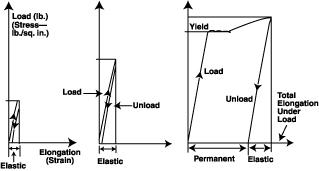 |
| Figure 1: To eliminate the influence of the specimen size, the test load is divided by the area of the original specimen cross section. The load and the corresponding elongations can be measured and plotted in diagrams. |
To safely withstand the expected maximum load without permanent deformation (and/or to stay within the specified deflection) is a basic requirement for any product. The resistance against the load is a function of the cross section and the mechanical properties (or strength) of the material.
The most important mechanical properties are yield strength, tensile strength, and elongation. These properties are established by testing. Tension is applied to materials to test their mechanical properties. The test specimens are cut and machined out from the material to be tested. After their cross sections are measured, the specimens are placed between the jaws of a testing machine. The gradually increasing load and the elongation are then checked.
To eliminate the influence of the specimen size, the test load is divided by the area of the original specimen cross section. The load divided by the area is the stress. For example, a 2,000-pound load on a test specimen with a cross section of 0.1 square inch will create a stress of 20,000 pounds per square inch (2,000 0.1 = 20,000). The load and the corresponding elongations can be measured and plotted in diagrams (see Figure 1). In many cases, the yield limit is clearly recognizable on the graphs.
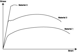 |
| Figure 2: When comparing the stress/strain diagrams of different materials, it is obvious that the low-strength, high-elongation material (Material 1) will have a different diagram than a higher-strength, less-elastic material (Material 2). A high-strength, low-elongation material (Material 3) will provide a different stress/strain graph. |
After a certain amount of yield, the load has to be increased to increase the elongation. Under stress, the specimen elongates; at the same time, its cross section decreases evenly. At one point, however, the test specimen cross section begins to decrease visibily. In technical terms, it starts to neck. Because of the reduced cross section at the necking, elongation continues to increase, even at a reduced load.
Finally, the specimen will break. The maximum load divided by the original cross section gives the maximum tensile strength of the material.Comparing the stress/strain diagrams of different materials (see Figure 2), shows that the low-strength, high-elongation material (Material 1 on the graph) will have a different diagram than a higher-strength, less-elastic material (Material 2). A high-strength, low-elongation material will again provide a different stress/strain graph (Material 3).
Figure 2 also shows that Materials 2 and 3, assuming that both are steels, have the same slope up to the yield point. This means that the elongation created by a given load is the same for both the low-strength and high-strength steels. Of course, the high-strength material will accept a larger load than will the low-strength material.
The slope representing the ratio between strain and stress expresses the elastic modulus (E) and is almost identical for all steels (approximately 30,000 by 100,000 pounds per square inch [PSI]). Therefore, a mild steel wire and a spring steel wire with the same cross sections will deflect the same amount under the same load, regardless of their yield or tensile strengths. However, higher-strength steels can carry higher loads and will remain elastic under loads that would permanently deform lower-strength steels.
Assume that Material 1 in Figure 2 is aluminum and has a different stress/ strain slope from steel. The different angle of the slope means that the aluminum's elastic modulus is different from steel's—actually, about one-third of steel's—so under the same load, all aluminum specimens deflect about three times as much as steel.
Not all materials display such a definite yield stress point as mild steel. It is generally accepted that the stress which creates 0.2 percent elongation will be the yield stress.
Elongation (e) normally is expressed as the ratio of the permanent elongation divided by the original specimen length. The measured permanent elongation includes the increased elongation at the neck, so shorter specimens provide relatively larger elongation. North American standards specify that elongation should be measured in 2- or 8-inch lengths.
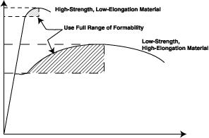 |
| Figure 3: This stress/strain diagram reveals that the larger the difference is between the yield and the maximum tensile stresses, and the larger the elongation, the better the chance of successful roll forming. |
In well-designed products, the actual stresses never reach the yield stress. Therefore, products are not permanently deformed under the maximum load. Only accidental overloads such as crashing a car or overloading a structure will create permanent deformation.
All metals, however, must be roll formed with stresses above the yield stress. Material formed with a stress below yield will spring back to its original shape. However, if the forming stress exceeds the maximum tensile stress, the product will crack and tear during forming.
The stress/strain diagram in Figure 3reveals that the larger the difference is between the yield and the maximum tensile stresses, and the larger the elongation, the better the chance of successful forming. It is difficult, if not impossible, to form metals with extremely high yield and tensile stresses and with near zero elongation. These materials will crack at the bend lines because the elongation created by the bending is larger than the maximum elongation of the material.
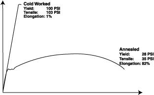 |
| Figure 4: After annealing, the high-yield, high-tensile, low-elongation metal becomes elastic and has low yield, low tensile strength, and low elongation. |
Some material can be formed with a zero inside radius (folded back on itself) without outside cracks. Others may require an inside radius equal to one, two, or more times the metal thickness. Steel with 80,000- to 100,000-PSI yield strength and about 2 percent elongation may require a minimum inside radius equal to or larger than four times the material thickness, or r = 4t.
The microstructure of the material also can affect cracking. Large, rough inclusions and certain alloying elements can contribute to cracking, but with proper alloying and treatment, the inclusions can be controlled and the minimum bending radius of some high-strength steels (up to 200,000-PSI yield strength) can be formed with an inside radius equal to four times the metal thickness.
The yield and tensile strength of a material usually can be increased by cold working, alloying, heat treating, and combinations thereof. For example, bending a piece of wire several times back and forth at the same place will harden and eventually break the wire. The reason for the breakage is the repeated bending, which is cold working. With each bend, the wire gets harder and its elongation is reduced until it cannot take any more cold work and it breaks.
The same phenomenon occurs when metals are rolled. To achieve the specified material thickness, the metal strip is passed through a pair of rolls with decreasing gaps between them. After a certain amount of cold reduction, the metal becomes so hard that rolling cannot be continued without cracking the strip.
Some of the cold-worked metals—often called skin-rolled, 1/4, 1/2, 3/4, or full hard, depending on the degree of cold work—are used by the industry. Most of the metals used, however, are heated to a higher temperature, or annealed, before they are shipped to users. During annealing above a specific temperature and time, the long, elongated, and hardened crystals recrystallize and acquire new and more elastic properties. As a result, the high-yield, high-tensile, low-elongation hardened metal after annealing is again elastic and has low yield, low tensile strength, and long elongation (see Figure 4).
The annealing and recrystallizing temperature for steels is about 1,100 to 1,400 degrees Fahrenheit (590 to 760 degrees Celsius) and about 650 to 800 degrees F (345 to 425 degrees C) for aluminum. If metal is deformed plastically above the annealing temperature (for instance, forged or hot-rolled), then the hardening caused by the work is annealed immediately. Therefore, the mechanical properties of hot-worked material are very similar before and after the process, although the shape of the crystals changes.
Hot working requires less force, and it is possible to achieve more thickness reduction at each forming pass. During rolling, the metal thickness is reduced gradually, and the strip gets longer and longer, increasing its surface. After a while, the surface and the related heat loss become too large to continue the rolling at the elevated temperature. Cooling is usually the limiting factor for hot rolling. Therefore, hot-rolled steels typically are available only in thicknesses greater than 0.060 to 0.080 inch.
Pure iron is not used by the sheet metal industry. All commercially used steels have a small percentage of carbon, as well as different impurities absorbed by the iron during the steel-making process. Even a very small amount of impurities, such as sulphur or phosphorous, can influence (usually reduce) certain properties of the steel. Therefore, these impurities are controlled carefully.
Carbon also has a major influence on several properties. The so-called mild steels, with carbon content not exceeding about 0.20 percent, can be formed and welded easily, but their hardness and strength cannot be increased by heating and quenching (heat treatment).
Steels with higher carbon content (about 0.4 to 1.0 percent) have higher yield and strength and lower elongation. They cannot be welded with the usual processes, but they can be heat-treated. Many spring steels belong to this group.
The commonly used American Iron and Steel Institute (AISI) specifications, such as C1008, C1010, C1020, etc., refer to the carbon content. The carbon content of these steels does not exceed 0.08, 0.10, and 0.20 percent, respectively.
Because the carbon content and the mechanical properties are related to each other, designers sometimes specify the carbon content to achieve good formability or high strength. Controlling the chemical composition costs the mills more, so buyers must pay more for metal whose chemical composition has been specified.
Different metallic coatings have been developed to prevent rusting of carbon steels. Tin, chromium, zinc, aluminum, and other metals are used for this purpose. Metallic coatings can be applied, for example, by dipping the steel into liquid metal, or by the electrolytic process, vapor deposit, hot spray, lamination with fusion bond, or chemical bond. In all cases, preparing and cleaning the steel surface are essential.
The most widely used metallic coating is zinc. Galvanized steel is produced when the steel is covered in molten zinc or zinc alloy, either by hot dipping or the electrolytic process. In the case of hot dipping, the adherence of the zinc to the steel depends on the steel and zinc temperature, immersion time, alloying elements, and surface preparation. The thickness of the zinc coating also is controlled by the same factors, as well as by the distance of the applicators or wipers during continuous hot-dip galvanizing.
Galvanized steel can be roll formed just as well as uncoated steel, but the zinc pickup on tooling and damage to the coating must be prevented. Zinc pickup is due mainly to the smearing or cold welding effect caused by the speed differential between the rolls and the formed strip and is accelerated by the roll pressure. It is cumbersome and dangerous to remove the built-up zinc from the rolls. The best way to prevent zinc buildup is to use good lubrication combined with properly designed and set up tools.
There is almost no difference between roll forming hot-dipped or electrolytically coated steel if the coating has the proper adherence. Careless metal preparation and incorrect coating procedures can lead to the zinc peeling off the product. Wiped coated steels (the zinc is wiped off after hot dipping) create no problems during roll forming.
Zinc alloy and aluminum-coated steels behave similarly to the galvanized steel and can create the same problems. Metal pickup can be avoided by using the same precautions as those recommended for zinc coating.


The Fabricator is North America's leading magazine for the metal forming and fabricating industry. The magazine delivers the news, technical articles, and case histories that enable fabricators to do their jobs more efficiently. The Fabricator has served the industry since 1970.
start your free subscription
Easily access valuable industry resources now with full access to the digital edition of The Fabricator.

Easily access valuable industry resources now with full access to the digital edition of The Welder.

Easily access valuable industry resources now with full access to the digital edition of The Tube and Pipe Journal.

Easily access valuable industry resources now with full access to the digital edition of The Fabricator en Español.
In this episode of The Fabricator Podcast, Caleb Chamberlain, co-founder and CEO of OSH Cut, discusses his company’s...


