


President
 |
You may have found yourself saying, "I need to make an engineering change to my roll form tooling, but I don't have the roll tooling designs or drawings." Maybe you have a product change; or the tooling is worn out, chipped, or broken; or your company just needs to improve the tooling.
When you are faced with this situation, you have to start at the beginning, basically, and reverse-engineer the complete set of roll form tooling.
Depending on a couple of factors, the roll form tooling may be recut and dropped, or decreased, in diameter to eliminate wear. The first consideration is the vertical range of your roll form equipment. The vertical range (centers) is the distance between the top spindle and the bottom spindle, and on most machines it is adjustable (see Figure 1). A large vertical range allows for recutting of the roll, but a very small vertical range does not allow for diameter changes, which means the roll tooling must be replaced when it becomes worn.
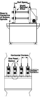 |
| Figure 1 Measurements must be taken at the vertical centers, horizontal centers, spindle diameter, amd roll space. |
The second consideration is spindle wear. If the roll form tooling has been run without keys in it, the bores of the roll tooling may be worn more than the specifications allow, which means the bores must be replaced or reconditioned. (Keys are the square pieces of cold-rolled steel that are inserted into the keyways of the roll tooling and the spindles to prevent the roll tooling from spinning on the spindles.) If the bores are overworn because they were allowed to spin on the spindle of the roll former, they will have to be ground, then hard-chromed, and ground again to achieve the precision fit required between the bore on the roll tooling and the spindles on the roll former.
You need to gather as much information about your roll form tooling and equipment as possible before you can get started. Measure and record:
It is important to know what steel grade the roll form tooling was made of originally. In the past many sets of roll form tooling were made out of tool steels that would case-harden only when heat-treated, meaning that the hardened surface was only about 1¼32 inch deep. Roll form tooling constructed this way cannot be recut; it has to be replaced. If the roll form tooling is made out of tool steel that can be through-hardened, the chances of being able to recut it are better.
 |
| Figure 2 Split contruction is better-suited for recutting than one-piece construction. |
It??s also important to know how your current roll form tooling is built. Many times roll form tooling is built in a way that allows it to be recut easily. A roll tooling set that is built with many splits or individual pieces is better-suited for recutting than a set that has a one-piece roll construction (see Figure 2). One-piece roll construction does not allow for easy changes, and if a change or wear in the roll form tooling is extensive, replacement is required.
The roll designer reviews the product drawing and final profile to generate the new roll form tooling drawing. Once the designer has this information, he can determine the practicality of changing the roll form tooling.
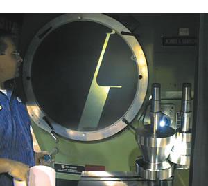
At this point the roll form tooling has to be shadow-graphed and measured (see introductory photo). Each pass and each roll must be put into an optical comparator that projects an image scaled 10 times the original size onto a screen. This image has to be traced by hand to examine the current condition of the roll form tooling and compared to the product drawing.
Typically this can be done in about a week, depending on the size of the roll form tooling and the number of forming passes. Companies that offer this service can work with the customer to minimize the amount of lost production time by doing a few passes of roll form tooling at a time.
 |
| Figure 3 |
After the shadow-graph tracing is complete, the roll diameter, roll width, angles, and bore size have to be measured and recorded. This information is used in conjunction with the tracing to develop the CAD files for each roll and forming pass. At this point the roll designer also looks at the tracing to determine the amount of wear and how much the roll diameters have to be decreased to eliminate the wear or chips in the roll form tooling. If some of the rolls are worn more than the others, the designer may elect to replace a few rolls rather than recut the entire set.
Once all this information is collected and the decision is made to recut or replace the roll form tooling, the designer uses CAD to draw the roll form tooling flower (see Figure 3).
 |
| Figure 4 The CAD drawings that are developed must show measurements, specs, and details for each pass. |
After the flower pattern is determined, the roll designer inputs the data from the tracings and the measurements into the CAD system to produce the roll form tooling design. The math data generated will be used in the CNC turning centers to recut or make new rolls as needed (see Figure 4).
If the roll former has additional stations, usually extra passes can be added at strategic spots that can help reduce wear, improve part quality, or reduce production problems. For example, if a lot of forming is being done between passes 5 and 6, an extra pass can be added between these passes to help slow down the forming. These types of ideas can help improve production issues and part quality.
If you have added side roll stands, supports, or straighteners to work in conjunction with the roll form tooling, the roll designer needs to have as much information about them as possible so they can be made to fit if any changes or replacements are needed.
Obviously, a lot of time and effort go into reverse-engineering a set of roll form tooling and reproducing the design. However, once the design is complete, performing an engineering change, replacing or recutting damaged tooling, or duplicating a set of tooling will be easier the next time.
Steve Ebel is president of Roll Form Solutions, 1130 E. Mt. Garfield Road, Muskegon, MI 49441, 231-799-9551, fax 231-799-9559, steveebel@rollformsolutions.com, www.rollformsolutions.com.
River City Roll Form Inc., 130 E. Mt. Garfield Road, Muskegon, MI 49441, 231-799-9550, fax 231-799-9559, info@rivercityrollform.com, www.rivercityrollform.com.


The Fabricator is North America's leading magazine for the metal forming and fabricating industry. The magazine delivers the news, technical articles, and case histories that enable fabricators to do their jobs more efficiently. The Fabricator has served the industry since 1970.
start your free subscription
Easily access valuable industry resources now with full access to the digital edition of The Fabricator.

Easily access valuable industry resources now with full access to the digital edition of The Welder.

Easily access valuable industry resources now with full access to the digital edition of The Tube and Pipe Journal.

Easily access valuable industry resources now with full access to the digital edition of The Fabricator en Español.
In this episode of The Fabricator Podcast, Caleb Chamberlain, co-founder and CEO of OSH Cut, discusses his company’s...


