


Engineer, Technical Services
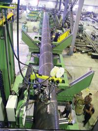
Figure 1: Skyline Steel’s Cartersville, Ga.-based facility has been making spiral pipe with the same mill equipment that was originally installed in 1992.
The large-diameter pipe used for the transmission of gas and oil traditionally has been made using either the longitudinal or spiral welding fabrication technique. Historically, spiral welded pipe was of low-grade steel and used mostly for casings, bridge foundations, and water transmission.
Skyline Steel, a subsidiary of ArcelorMittal, recognized in 2001 that for it to win contracts for high-end projects requiring high-pressure and high-strength steel spiral pipe, it would need to become more competitive in price. The quality of the pipe the company shipped was never a problem; the amount of time and money it took to fabricate these high-quality pipes was. Too much rework was taking place.
The manual welding process at Skyline Steel was tedious. To achieve guaranteed full-penetration, defect-free welds as required by the API 1104 Standard for Welding of Pipelines, the operator had to be completely vigilant and dedicated to watching the welding during the process. In addition, redundant nondestructive examinations took place to ensure quality. Of course, for those welds that did not meet the required quality standards, operators sent the pipe for rework.
Skyline Steel has been making spiral welded pipe since 1992 (Figure 1). The goal of spiral pipe manufacturing (Figure 2) is to produce pipe continuously even to the point of splicing coil ends together, so the forming, welding, and cut-to-length operations are not interrupted. This approach produces the maximum feet of pipe per day.
The production rate before 2001 varied depending on the diameter, material, and quality requirements, but usually was from 2.5 to 3.5 miles per week. While these numbers were acceptable, Skyline management wanted to see production improvements to better position the company in the future. To achieve any significant improvement, Skyline knew a major change in its manufacturing process was necessary.
Skyline looked at its whole operation, both welding and nonwelding, to determine where best to invest to achieve a real increase in process capability and productivity. In the welding area, the company looked at new types of power sources, new welding processes, different welding wires, and changes to the weld parameters themselves.
The company also became convinced that the capability of the weld was affected directly by the skill and diligence of the operator trying to keep the wire in the weld joint—a difficult task in a hot, stressful mechanized submerged arc welding environment. To change this, management considered laser vision seam tracking of the welds and later determined the technology would make the biggest impact on weld quality and productivity.
The camera technology used for seam tracking and weld inspection is based on the principle of laser triangulation. A low-power laser beam is projected onto the surface of the part, and the reflected scattered light is delivered back in the form of an image onto a complementary metal-oxide semiconductor sensor. The controller then extracts signals from the image that can be used for either tracking or weld inspection purposes (Figure 3).
Before seam tracking of the pipe's outside-diameter groove weld can take place, the inside weld is made first. The outside diameter tracker is mounted about 4 inches to 6 in. in front of the welding torch and tracks the joint. Via a delayed shift, the tracker tells the two axis—cross-seam and up/down—slides to apply the correct trajectory shift when the wire reaches the point where the variation was measured. In this way, the wire is kept exactly in the correct position in the joint for maximum weld penetration. Figures 4a and 4bshow the equipment at work.
Before Skyline Steel could embark on its weld improvement project, it needed to select the right technology partner for its laser vision seam tracker.
Figure 4a and 4b: The seam tracking unit can be seen on the welding manipulator from a distant and up-close view.
After reviewing technology suppliers recommended by industry contacts or found on the Internet, company management selected three companies, which were then invited to the plant to learn more about Skyline Steel and the spiral welding process.
Based on the budgetary quotes received, the Skyline Steel team eliminated one of the three finalists. They then traveled to the facilities of the final two technology suppliers to evaluate their capabilities in engineering, production, quality control, and service. They also followed up with references to discover how successful those pipe fabricators had been with similarly installed equipment.
With the due diligence complete and formal quotes in hand after the three-month process, Skyline Steel selected Servo-Robot Inc. as its partner on the project. A purchase order for two laser vision seam tracking systems was issued with plans to place the units on two existing manipulators for outside-diameter welding.
Preparation for installation took place during the eight-week time period Servo-Robot required to build the systems. Skyline Steel prepared in the following ways:
Once the physical installation was complete, the AUTO-TRAC system was programmed, and trial pipe was tracked to verify proper results were attained. During this time, a couple of issues had to be addressed.
The location of the camera needed to be configured so that it was far enough in front of where the submerged flux would flow. If the camera position were not optimized, the flux could fall down in front of the camera's field of view and confuse things. If the camera were too far out in front, the orientation with respect to the torch could be unwieldy.
The tracking parameters needed to be fine-tuned and a couple different programs created to handle subtle differences in the joint between different pipe diameters, joint preparations, and inside weld penetration into the top side grooves.
Real production welding then began with the operator still monitoring the process, but no longer steering the torch to keep the wire in the joint. After a very short time, the operator was redeployed to another area of the plant. Over time a few different seam tracking programs were made to accommodate further variations in pipe diameters and joint preparations.
Skyline Steel management was pleased with the addition of the seam tracker and believes it achieved a payback on the equipment in less than one year. The company reduced welding defects, such as lack of full penetration, by approximately 50 percent to 60 percent; increased the rate of travel speed by 25 percent to 30 percent; reduced rework and re-inspection caused by welding defects; and eliminated labor cost because a person was no longer needed to watch the welding torches and constantly steer the manipulators. Additionally, Skyline Steel began chasing after new business in the area of high-quality, full-penetration pipe.
The success at the Cartersville, Ga., plant led to the installation of several more units for both outside- and inside-diameter welding over the next few years at other U.S. plants. The big difference with the inside-diameter welding is that there is an opportunity (in addition to tracking) to use the mismatch/gap data to drive the bridge control, which changes the angle that the steel (skelp) is oriented to the weld joint. Figure 6 shows the concept of how the steel is fed. Traditionally, this was manually controlled, which led to overadjustments or changes that weren't made in a timely fashion. Now the exact measurement data is fed back in a timely manner, so the equipment adjusts the skelp entry angle in small increments, improving the weld integrity.
The pipe producer has additional opportunities to use the laser vision technology to improve the overall welding and dimensional quality of the finished pipe:
Figure 6: Skyline Steel is using the laser vision seam tracking equipment on ID welding at its other U.S. plants. This schematic shows how the weld is made.

The Fabricator is North America's leading magazine for the metal forming and fabricating industry. The magazine delivers the news, technical articles, and case histories that enable fabricators to do their jobs more efficiently. The Fabricator has served the industry since 1970.
start your free subscription
Easily access valuable industry resources now with full access to the digital edition of The Fabricator.

Easily access valuable industry resources now with full access to the digital edition of The Welder.

Easily access valuable industry resources now with full access to the digital edition of The Tube and Pipe Journal.

Easily access valuable industry resources now with full access to the digital edition of The Fabricator en Español.
In this episode of The Fabricator Podcast, Caleb Chamberlain, co-founder and CEO of OSH Cut, discusses his company’s...


