


Cutting structural steel to length; The sheer facts of shear tooling and processes
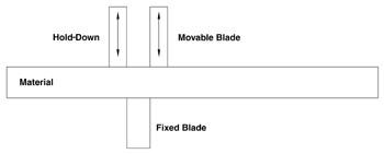 |
| Figure 1: Single-cut shearing requires a hold-down device on the material infeed side of the shear. |
In the fabrication of structural steel, the first process usually is cutting-to-length. The methods typically employed are sawing (cold sawing or band sawing), burning (plasma or oxyfuel), and shearing.
Shearing generally is limited to miscellaneous structural steel parts. It is not used on larger structural elements, because the force required and the resulting cut quality limit economic and practical feasibility. Structural elements that are practical candidates for shearing include:
• Angle Iron 8 in. and less
• Channel 12 in. and less
• Flat stock 12 in. and less
• Beams S 5 x 10 in., M 4 x 13 in., W 4 x 13 in.
Shear Tooling
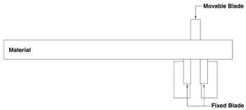 |
| Figure 2: Unlike single-cut shearing, double-cut shearing does not require a hold-down device. |
A tool steel such as S-7 generally is used to manufacture the tooling, or knives. The knives are machined to the required tolerances and then heat-treated to a hardness specification of 52 to 56 Rockwell C scale (HRC). During heat-treating, they change shape slightly. A grinding operation returns the knives to the specified finished tolerance.
A tooling set comprises a fixed knife and a movable knife. The running clearance between the fixed knife and the movable knife should be 10 percent of the structural element's material thickness.
Shearing Processes
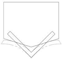 |
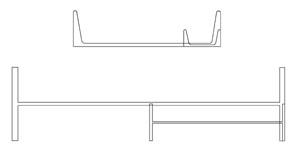
| Figure 3: A blade with a rake angle distorts the slug only—the finished part remains flat. |
Currently two shearing processes are used to cut miscellaneous structural steel elements. They are single-cut and double-cut shearing.Single-cut Shearing. The single-cut process uses one fixed blade and one movable blade. A material hold-down device on the material infeed side of the shear keeps the material properly positioned during the shearing process (see Figure 1).
Double-cut Shearing. The double-cut process is uniquely different from the shearing process employed to cut plates or barstock. Double-cut shearing uses three cutting tools—the upper, or movable, blade functions like a punch; the two lower, or fixed, knives act like a die (see Figure 2). The upper (movable) blade generates a material loss equal to the blade thickness for each cycle.
The workpiece is supported on both sides of the upper knife, so a material hold-down is not required. Because the upper blade functions as a punch, the minimal shear length cannot be less than the thickness of the upper blade.
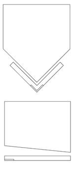 |
| Figure 4: For parts with a uniform profile, one blade can process a range of sizes. |
Material Thickness. The thickness of the upper blade is the maximum thickness of material that can be sheared with this tooling configuration. For example, if double-cut tooling is used to shear flat stock up to 1 in. thick, then the upper blade should be at least 1 in. thick. This 1-in.-thick blade generates a material loss, or kerf, of 1 in. for each shear cycle, regardless of the material's thickness.
Material loss can be a critical factor, depending on the application. For example, if a finished part is 20 ft. long and the upper knife is 1 in. thick, material loss from the double-cut shearing process is a negligible 0.4 percent of the total length. When 10-in.-long parts are cut, material loss is significant at 10 percent of the total length.
Rake Angle. The upper blade of a double-cut shear can use a rake angle, which reduces the cross section that is sheared at one time. Reducing the cross section to be sheared at once reduces the tonnage required substantially.
The distortion that results from using a rake angle is reflected in the slug, or waste material (see Figure 3). The ability to contain all the distortion within the slug produces an exceptionally flat finished part. However, because this process shears the material progressively, it requires a longer stroke than conventional or single-cut shearing.
Shearing Channels, I beams
The uniform profile of flats and angles makes them ideal for shearing—one set of tooling can accommodate a range of sizes (see Figure 4).
 |
| Figure 5: For parts with a nonuniform profile, a unique set of shear tooling is required for each part. |
This is not the case, however, when the application involves channels or I beams. When the depth of a channel or I beam changes, the distance from one flange to the other also changes. Different locations of the flanges and the height of the web, in the case of an I beam, dictate a unique tooling geometry for each section size (see Figure 5).
In addition to the beam or channel depth, the weight per foot also changes the cross section of the member. These differences of depth and weight mandate that a unique set of upper and lower knives be employed for each size and weight of channel and beam.
Tolerating Variations in Structural Sections
Unfortunately, the challenge of matching the profiles of the knives to the section to be sheared does not end with the size and weight of the section. During mill rolling of raw material, the rolls that are used by the steel mill will wear from use. This wear results in sections that are slightly larger than the targeted dimensions of the member. Slight variations in mill tolerance are normal and considered acceptable.
Understanding the dynamics of mill tolerance, designers of single-cut tooling for channels and I beams must provide an opening for each size and weight of section that is rolled. Unfortunately, this mill tolerance is variable, and the required tooling opening to accommodate this tolerance negatively affects the quality of the sheared cut.
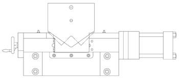 |
| Figure 6: Double-cut tooling for channels and some I beams incorporate a hydraulically adjustable side anvil. |
Double-cut tooling arrangements for channels and some I beams address this mill tolerance problem in a unique fashion. These die sets incorporate a hydraulically adjustable side anvil (see Figure 6). This design not only accommodates a range of channels (4 to 12 in.), but its hydraulic side-clamping design addresses the mill tolerance challenge.
This adjustable die set ensures that the side anvils are clamped tightly to the flanges of the member for each stroke and compensates for any mill rolling tolerance.
Running the Gamut
Machine types, tooling, and options available for cutting structural steel members run the gamut from simple to complex to accommodate various cutting scenarios. Selecting the process—single-cut versus double-cut, rake angle or no rake angle, or using another method altogether, such as sawing or flame cutting—that best addresses the application criteria requires first establishing the cost and engineering constraints of the finished part.
Peddinghaus Corp., 300 N. Washington Ave., Bradley, IL 60915, phone 815-937-3800, fax 815-937-4003, web site www.peddinghaus.com. Peddinghaus designs and manufactures equipment for marking, drilling, sawing, punching, shearing, burning, cambering, and handling structural steel and plate.
About the Author
About the Publication
subscribe now

The Fabricator is North America's leading magazine for the metal forming and fabricating industry. The magazine delivers the news, technical articles, and case histories that enable fabricators to do their jobs more efficiently. The Fabricator has served the industry since 1970.
start your free subscription- Stay connected from anywhere

Easily access valuable industry resources now with full access to the digital edition of The Fabricator.

Easily access valuable industry resources now with full access to the digital edition of The Welder.

Easily access valuable industry resources now with full access to the digital edition of The Tube and Pipe Journal.

Easily access valuable industry resources now with full access to the digital edition of The Fabricator en Español.
- Podcasting

In this episode of The Fabricator Podcast, Caleb Chamberlain, co-founder and CEO of OSH Cut, discusses his company’s...


