


Contributing Writer
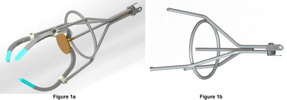
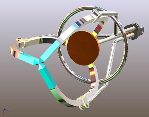
Figure 1a
This example product uses bent tubing that is welded together. The assembly has three moving arms.
Figure 1b
The frame for the grappling hook is made from bent aluminum tubing and machined and stamped components.
Figure 1a is this month’s target design. In our working scenario, we are responsible for fabricating the items that are made from tubing of various profiles. Figure 1b shows the primary frame for the gripper assembly shown in Figure 1a.
It is convenient—and unusual—to see the finished design while considering how to develop the model in 3-D CAD. Most often someone is inventing the product while completing the modeling. We’re offering a sneak peak of the finished CAD to provide context for some of the technical narrative.
The components of the frame shown in Figure 1b are to be welded together. The pivot parts and lift connection components are machined or stamped parts. All of the tubing is the same size; most of it is bent. Only one piece is a straight section.
A tube bending machine needs data to know how to manipulate the workpiece. This includes feed distance, rotation angle, bend radius, bend angle, bend speed, dwell, and so forth. A CNC may be able to import a STEP file and convert it into the required robotic motions. Manual bending machines rely on skilled operators to interpret manufacturing drawings.
Either way, the methods used to invent and document the product in 3-D CAD can streamline the overall manufacturing process. In our scenario, we don’t have a specific bending machine controller in mind, so our deliverable will be a STEP file for manufacturing. Our focus will be on 3-D CAD modeling techniques.
(In the process of producing the illustrations for this article, a specific brand of CAD was used. Many of the general planning concepts will apply to other brands of CAD.)
The “Do My Job” button that was used to produce Figure 1a is actually a sequence of steps. The last step, which closely resembles a DMJ button, involves selecting a profile for the tubing and clicking on lines that represent the paths that those profiles should follow. The tricky bit from the 3-D CAD point of view is sketching the paths.
We could have modeled the object shown in Figure 1a as a collection of individual parts and then put them together into an assembly. This is a no-need-for-Weldment-tool CAD technique. All of the tubing parts shown could have been modeled with simple sweeps along 2-D sketches. That approach slows down as the complexity of the future edits and design changes.
Our goal is to develop a 3-D CAD model in a short time that works well. Efficiency in edits is a blessing, especially in the early stages of product development. Some setup and overhead are required, but the last step of using the Weldment tool is simply entertaining to us CAD jockeys.
Even though the individual tubing parts in Figure 1a could be modeled with 2-D sketches, we are going to model all of the tubing parts in a single sketch. The core technique used is the 3-D Sketch. Figure 2 is a sneak preview of the planes used to model the weldment in Figure 1a.
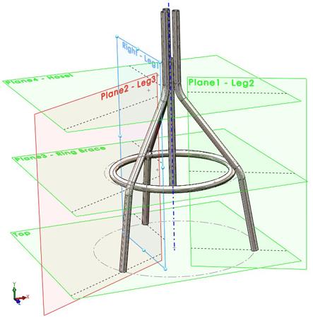
Figure 2
Construction geometry in the form of planes is useful when planning and drawing in 3-D space.
Two-dimensional sketch techniques—as opposed to 3-D sketch techniques—are familiar to the CAD jockey. For example, select a face or plane, draw lines and arcs, and exit the sketch. Three-dimensional sketch techniques can be nearly identical, but a few 2-D sketch relationships exist that are not available in 3-D sketches—symmetry relations, for example. This is not a big deal if the right construction geometry is available to help in the construction of the 3-D sketch.
It is possible to use the 3-D Sketch tool without referencing any planes. However, sketching in 3-D space requires masterful attention to context. What you see projected in the graphics window is not necessarily what you get in 3-D space. The use of a plane in a 3-D sketch makes the 3-D sketch no more difficult to complete than a 2-D sketch.
Figure 3a strips away the planes and tubing and shows only the paths for the tubing. For this example frame, the paths sketched are the centerlines for all of the tube segments. The Weldment tool allows you to control which part of the profile follows the path. In other words, the path does not have to be the centerline; it can follow any part of the structural element.
Figure 3a is the 3-D sketch that is driving the weldment shown in Figure 1a. The planes shown in Figure 3b represent a powerful 3-D CAD sketching technique that made the production of Figure 3a easier.
Here’s a summary outline of how the planes in Figure 3b were modeled:
As the definition of such reference planes progresses, it may be useful to stretch the size and position of the plane to approximate the boundaries of what is being modeled. Note that the intersection of two planes is automatically shown if you properly position their boundaries. These subtle hints help you visualize the relevance of the geometry to the functional design.
With the plane definition completed, the 3-D sketch shown in Figure 3b was started. To control the diameter of the gripper frame, we sketched a circle on the top plane and gave it a dimension. This circle positions the pivot points for the three gripper arms. Similarly, a circle was sketched on the ring brace plane and another sketched on the hosel plane to control the spread of tubes at the top of the frame. Note that all of those circles were sketched to have on plane relations along with having their centerpoints constrained to be coincident with the axis.
The path for the ring brace is sketched as an offset from the circle that controls the knee bends of the three legs. If the diameter of the tubing changes for the ring brace, this offset dimension will need to be changed to keep the tubes in proper position for welding.
To finish up the 3-D sketch, we draw the path for each leg separately. The basic process is to select a plane, draw the line segments, and add sketch relations to constrain the end points to the relevant elevation plane. With the addition of a few dimensions, this 3-D sketch is fully defined. Note that some of the sketched geometry is shown with construction lines; this is only for style and clarity. All of the lines in the 3-D sketch for a weldment can be solid.
This example project is too simple. All of our bent tube parts could be modeled without using 3-D sketches. In fact, our recommendation of constraining the sketch elements to planes may make it seem harder to model tubing that bends along three or more axes. Our contention is that the definition of additional planes would facilitate the modeling of more exotically bent sticks.
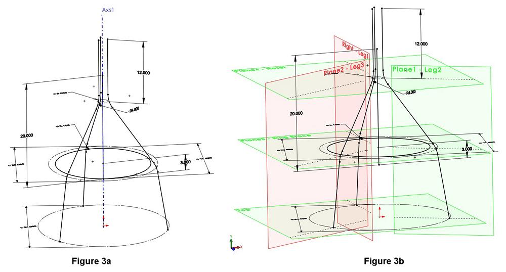
Figure 3a
This sketch shows the paths that the tubing sections will follow. A 3-D sketch can be difficult to interpret if you are looking at it with a 2-D monitor.
Figure 3b
Planes serve as construction geometry and make sketching in 3-D space much easier. The planes give depth and context
to the 3-D sketch.
As a side benefit of modeling with planes, the postprocessor for the CNC may be able to take advantage of that reference geometry. When drafting 2-D fabrication drawings, the reference planes are useful for section views as well as dimensioning.
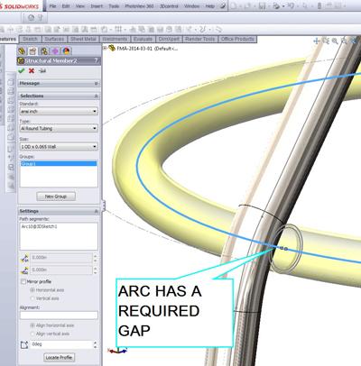
At last we arrive at the stage that amazes. Figure 4 is a screen shot of the conversion of the 3-D sketch into a bunch of things that look like bent tubes. This is the definition of Structural Members in a Weldment.
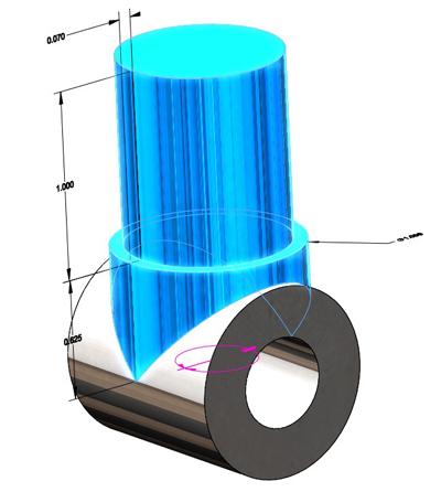
The Structural Member process involves selecting the profile for the desired tubing and then selecting the path for that profile to follow. One subtle nuance of the latest version of this software is to expand the way that weldment profiles are stored on disk by allowing the use of configurations in the profiles. In the old days, one needed a single file for each profile.
As a technique specific to this Structural Member, the line segments that make up the path for a single leg were selected as a Group. (See the Groups box to the left of the graphics window in Figure 4.) Four groups can be found in this Structural Member: three legs and the center guide tube.
Instead of using the Groups box, we could have merely selected the line segments for one leg and exited the Structural Member tool. We then would have relaunched the Structural Member tool and repeated for another leg and done so one more time until individual Structural Members are defined for each chunk of the weldment.
That method—only one functional chunk per structural element—allows you to change the profile for one leg, such as adjusting it to have a thicker wall, without affecting the other legs or parts in the weldment. That method is also slightly more laborious for the CAD jockey and also a tiny bit more work for the CPU. This is a matter of style and preference, and we chose a fork in the CAD path.
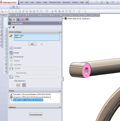
The ring brace shown in Figure 5 was defined as its own Structural Member. We could have included its definition in a group at the same time as we did the legs, but it made a better illustration to show the existence of a leg while selecting the path for the ring brace. Perhaps this will make it easier to change the material for the ring brace without messing up the legs. Scenarios are like that.
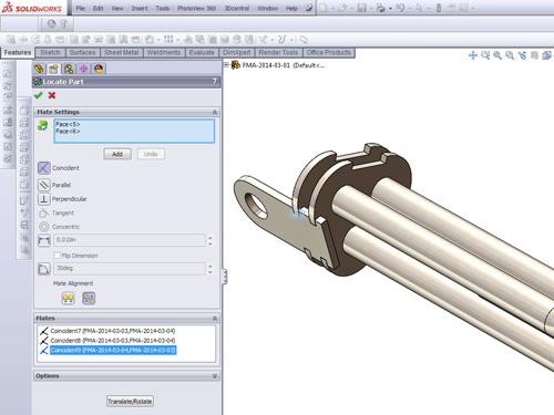
Before you know it, we’re going to have a full set of dinnerware. Figure 6a shows a stand-alone model for one of the pivots for the gripper frame. Figure 6b shows that part inserted and mated into the end of one of the leg tubes. In this example, we have inserted the pivot part into the weldment model. It now exists as a separate body from the bent tube parts and shows up in the Cutlist for manufacturing this weldment.
An alternative CAD technique to inserting a part into a weldment is to collect the parts into an assembly. Then the various components for the weldment show up in a BOM table instead of a Cutlist table. There are merits to this alternative: It is very conventional and familiar.
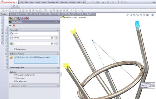
In Figure 6b we see that the inserted part can be mated in a way that is similar to a conventional assembly. In Figure 6c we see that that inserted body can be patterned in the weldment. In this example, the first pivot is patterned to complete all three that are required for this design. To complete the design, we model the other components for the lifting connections and insert them into the weldment as shown in Figure 7. The process of modeling a weldment involves a combination of 3-D sketching and manipulation of solid bodies within the weldment. Gnarly.
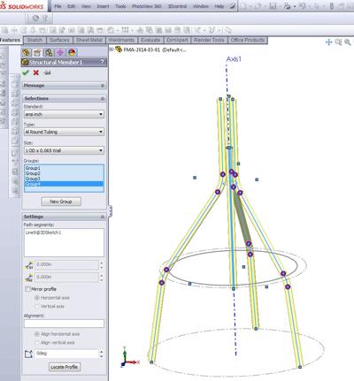
Figure 4
A screen shot of the Structural Member’s Property Manager shows the selection of line segments in groups to define pieces of bent tubing.
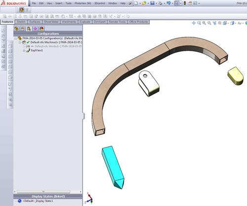
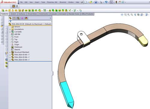
Have you ever taken a fork in a path in CAD and regretted it? Me too. With experience and luck you can avoid that diversion. In the current state of the CAD, the consequences of choosing multibody over conventional assembly are not too severe. Figure 8a is an exploded view of one of the gripper arm weldments. Figure 8b shows that arm in a collapsed state. The point is that documenting and illustrating a weldment is almost as easy as that for a conventional assembly.
The main difference is between a BOM and a Cutlist. A minor difference is editing a body in context compared to editing a part as a stand-alone file.
As a general guide, if the project required kinematics—that is, motion and moving parts—then assemblies have a lot to offer. In Figure 9, the assembly of the frame and arms has been manipulated to test the gripper’s functionality.
While the CAD technique of using assemblies has many good applications, if the parts are stuck and static—welded together, for example—then the convenience of modeling everything in a weldment can be a blessing.
Note that the Weldment functionality is not just for tubes. It can be used to model wire, rod, tube, or any extruded stick profile. Furniture as well as structural frames can be designed efficiently with this technique.
Gerald would love to have you send him your comments and questions. You are not alone, and the problems you face often are shared by others. Share the grief, and perhaps we will all share in the joy of finding answers. Please send your questions and comments to dand@thefabricator.com.


The Fabricator is North America's leading magazine for the metal forming and fabricating industry. The magazine delivers the news, technical articles, and case histories that enable fabricators to do their jobs more efficiently. The Fabricator has served the industry since 1970.
start your free subscription
Easily access valuable industry resources now with full access to the digital edition of The Fabricator.

Easily access valuable industry resources now with full access to the digital edition of The Welder.

Easily access valuable industry resources now with full access to the digital edition of The Tube and Pipe Journal.

Easily access valuable industry resources now with full access to the digital edition of The Fabricator en Español.
In this episode of The Fabricator Podcast, Caleb Chamberlain, co-founder and CEO of OSH Cut, discusses his company’s...


