


Contributing Writer
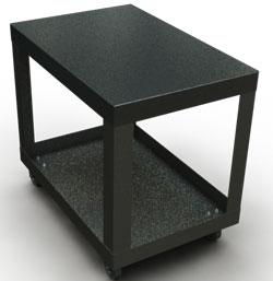
Figure 1: This is a typical shop cart made from two nearly identical pans and four identical legs.
The shop cart shown in Figure 1 is a pretty basic concept. Using it as a starting point, we have two objectives: Improve the design so it better suits our needs, and get in a little 3-D CAD practice.
As an apprentice, I helped sort through remnants of sheet stock so that the wiser heads could plan out how big the shop carts would be. Like most shops, we built stuff like this to fill the idle moments.
The casters usually were collected from the Surplus Store down on Alameda Avenue in Denver. The leg lengths were adjusted to match whatever casters showed up. The X-Y table size was tweaked to match the available scrap stock.
The basic approach to engineering was to use thick material and lots of welds—or bolts if Danny the welder was on vacation.
Nowadays, of course, shops don’t have piles of remnant inventory sitting around. Lean manufacturing has reduced the inventory to the point where shop employees glare at me if I snatch a sheet of anything without getting written permission first. We still occasionally need to build new shop carts, however, so the easiest way to get them started is to plan them out.
We want to use the sheet stock efficiently. We’ll be looking at the nesting of the parts in the raw sheet to make sure we’re maximizing both useful surface area on the cart, as well as minimizing raw material utilization. Perhaps for the first time ever, we’re going to make a standard-height shop cart that matches the load points on more of our machinery—places like discharge ports from tumblers, worktables on punch presses, and loading surfaces for press brakes.
We want to make sure that the corner joints are fabricated in the most reliable way. Nuts and bolts are an option. Welding, spot welding, and riveting might be better choices.
We’d also like some assurance that we’re using the right material thickness. We could just make everything out of 10 gauge, but if our casters are rated for only 300 lbs., is that really the best use of material? What if the boss said the budget limits us to 16-gauge steel? Where do we need to add flanges and ribs to stiffen the assembly to achieve the target load?
Then we need to consider the aesthetics. The open bottom pan shown in Figure 1 is a trash can on wheels. It has no handle. What kind of finish does it need? Will a bare metal top work, or does it need a skin of some other material?
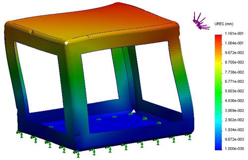
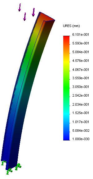
Figure 2 shows a displacement plot from SolidWorks® SimulationXpress®. In order to set this up, I created a simple model to represent the dimensional framework of the cart. This makes it easier for me to analyze it on my computer. Even though I am not simulating reality, the simulation does show that twisting and side loading represent the greatest threat to this design. The connection points between the legs and the pans are really important.
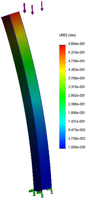
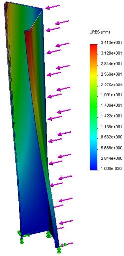
Figure 3a shows a similar plot showing a 16-gauge sheet metal leg with about 300 lbs. pressing perfectly against it—again, something that would never happen, but something to consider. This leg can support a huge vertical load, but is prone to bending under side load. In Figure 3b I’ve added some stiffening flanges and repeated the same study as in Figure 3a. No significant change in the ability to support a vertical static load was found.
In Figure 3c I changed the direction of load to press on the leg’s side. It twists very easily, with or without the stiffening flanges. From my practical experience, I’d say that a 27-in.-long, 16-gauge steel angle behaves pretty much like the simulation results predict. If I enter the load values correctly and set the fixtures up in a reasonable way, the simulation is very predictive.
In these examples, I’ve used rather arbitrary loads and directions. Nonetheless, we know we need to keep the legs from twisting (a middle shelf would increase the load-bearing capacity of the cart), and that the connection between the pans and the legs is all that keeps the cart from collapsing. Well, duh.
Next time we’ll check the nesting of the parts in a flat blank. We’ll talk about the design/process constraint too. For example, I’d like to use half-shears in connection between the legs and the pans, but metal cutting lasers don’t do that. Should we subcontract part of the fabrication of our shop carts?
Gerald would love to have you send him your comments and questions. You are not alone, and the problems you face often are shared by others. Share the grief, and perhaps we will all share in the joy of finding answers. Please send your questions and comments to dand@thefabricator.com.


The Fabricator is North America's leading magazine for the metal forming and fabricating industry. The magazine delivers the news, technical articles, and case histories that enable fabricators to do their jobs more efficiently. The Fabricator has served the industry since 1970.
start your free subscription
Easily access valuable industry resources now with full access to the digital edition of The Fabricator.

Easily access valuable industry resources now with full access to the digital edition of The Welder.

Easily access valuable industry resources now with full access to the digital edition of The Tube and Pipe Journal.

Easily access valuable industry resources now with full access to the digital edition of The Fabricator en Español.
In this episode of The Fabricator Podcast, Caleb Chamberlain, co-founder and CEO of OSH Cut, discusses his company’s...


