


Contributing Writer
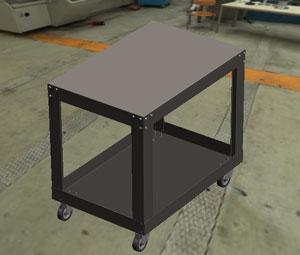
Figure 1: This is as “realistic” as the shop cart model needs to be.
Before we go any farther, let's make the following clear: Many CAM systems are very good at nesting parts on a flat blank for laser or CNC punching. I'm not proposing to use 3-D CAD as a replacement tool for nesting software. However, I am proposing that sometimes the raw stock available dictates the size parameters of the product's design.
We're working on a design for a shop cart similar to the one shown in Figure 1. With our 3-D CAD tool, we can model an assembly that shows the cart as realistically as time permits. The parts that make up that realistic-looking cart could be linked to each other. We might use such links to guarantee that various patterns of holes align between the ends of the legs and the top shelf. We could take those same sheet metal part models, unfold them, and insert them into a new assembly to create a nest of the flat layouts.
We then could arrange the parts by eye or by controlling dimensions to make the best use of the raw material as shown in Figure 2. Of course, we could insert that nested layout assembly into a drawing and then export the drawing as a DXF so the CNC programming could convert the nested theory into manufactured goods.
At an extreme, we could parameterize our part sizes to the raw stock size. If the stock size changes, then the parts adjust themselves to fit automatically.
All of that is a bit ambitious for one monthly article, so we'll postpone the flat-drives-the-cart discussion until next month. For now, let's consider one of several possible methods for creating a flat nest of sheet metal parts.
The 3-D CAD tool that I'm using allows more than one method for modeling products that are made up of parts. A multibody part is a single file that has more than one part in it; technically, each body could represent a finished component. An assembly made up of virtual parts is similar to a multibody in that all parts are kept in one file. However, the virtual parts behave just like ordinary parts, displaying some of the same attributes in kinematic mechanisms when it comes to mating. An assembly can be made up of other components, such as other assemblies, multibodies, or parts.
I'm going to avoid using multibodies in our cart project partly because, until recently, sheet metal fold/unfold and multibodies were not allowed in the same file. Even with the current release of the software being used for this design exercise, which calls for use of off-the-shelf and custom-made components, I like an assembly of parts because that modeling technique makes the creation of a bill of materials (BOM) very easy (Figure 3). Whether those parts are "virtual" or not is a matter of personal preference.
We're actually going to have two working assemblies for this project. One assembly as shown in Figure 1 will be the driver for our BOM as shown in Figure 2. We'll also employ it for production of assembly illustrations and mechanical drawings. It also will be useful for specifying the features that we want to tie together—such as keeping bolt holes in the floor in concentric alignment with mounting points on the casters. This BOM assembly will have all of the parts that comprise the cart—casters, bolts, and sheet metal.
The second nest assembly (Figure 4) will have just the sheet metal parts in it. We also will want those sheet metal models to be in their flattened state and assembled in a way that looks like a nested blank. For now we're going to use the BOM assembly to define the size and location of all of our features. The nest assembly is functionally just a report card on how well our design fits on a sheet of raw material.
We certainly don't need a computer to do this flat nesting, but it helps. And 3-D CAD is not the only way to visualize nested layouts. Sketching a handful of rectangular blocks in any 2-D drawing editor would take little time. Using a mainstream 3-D CAD system to create a nest of sheet metal parts is bordering on tool abuse. However, the technique we're demonstrating should allow us to toggle the part—while looking at the nest, mind you—between flat/ folded/shaded/wireframe. It parametrically links the finished assembly to the nested flat.
If this project required that we align burrs and faces or if embosses, countersinks, grain direction, or other orienting features were present, then we might find it handy to perform that toggle of the displayed part while evaluating and editing the nest. Note that one of the legs in Figure 4 is shown in its bent configuration.
Not all design projects require consideration of raw material utilization. In this instance, our shop cart project is undoubtedly a bit unusual. 3-D CAD can be used for nesting, but the manual process I'm describing would take a CAM system seconds and it took me lots of minutes.
We're going to use a pair of configurations to get the part model to toggle between flat and folded. For example, the Default configuration will show the folded part, and the Flat configuration will show the unbent part. When a sheet metal part is inserted into a 2-D drawing, my 3-D CAD software automatically creates and names a DefaultSM-Flat-Pattern configuration. That's a long name, but as long as we know what it is, we could use it.
To flatten a part, calculations must be processed for the bends to change all of their angles to 180 degrees. The bent part has this "processing" turned off by suppression. Toggling the suppression state of the bend processing moves the part between flat and folded.
We like convenience. The Flatten button is convenient and toggles the suppression of bend processing for us. If my sheet metal model adheres to the modeling rules, I can toggle the Flatten button to switch the model between flat and folded. That's all the button does: It toggles the suppression state of one feature listed in the Feature Manager history. We need more!
We need a way for our nest assembly to inform the part whether it should be flat or folded. The assembly can't click a button, but it can send a message to the part like "switch to your DefaultSM- Flat-Pattern configuration." So we're going to create a configuration in the sheet metal part and that configuration will remember the suppression state of the bend processing in order to create the unbent version of the part. As long as the part is told to be in that DefaultSM-Flat-Pattern configuration, it will be flattened due to bend processing.
Clicking on the Flatten button would have no useful effect while the part exists in this flat configuration, by the way. That button click would toggle the suppression state, putting the part into a bent condition. Why show a bent part in a configuration named "flat"? Click one more time to return the part to the flat condition in the flat configuration, and don't let on that you wasted a pair of clicks.
The longhand method of creating a configuration is to switch to the Configurations Manager tab (Figure 5a), click on the right mouse button, select Add a Configuration, fill in the form (Figure 5b) to give it a nice name—perhaps DefaultSM-Flat-Pattern—and click OK to dismiss the form. With your DefaultSM-Flat-Pattern configuration active, switch back to the Feature Manager tab and unsuppress the Flat-Pattern1 feature. When you do that, the part will unfold (). If you click on the Configurations Manager tab and make the default configuration active instead, the part should switch back to the folded state because the Flat-Pattern1 feature is remembered in the suppressed state by the default configuration.
Now that all of our parts have both a flat and a folded configuration, we can insert them into our new nest assembly. I like splitting the screen as shown in Figure 7 so I can see the BOM assembly on one side and the nest assembly on the other. Then it is just a matter of dragging and dropping the parts from one assembly to another. The time-consuming bit is mating all of the parts to give proper nesting alignment as shown in Figure 8.
But wait! What will become of the external links that tie the mounting holes together? Relax! They are defined in the context of the BOM assembly. If the BOM assembly is open in RAM at the same time that the nest assembly is, the nest assembly will be up-to-date. At all other times—when the BOM assembly is closed—the external links in the nest assembly will be out-of-date. To put it another way, the nest will be a snapshot of the BOM as of the last time that the BOM was saved.
But wait! I might want those links to be dead. What if the nest assembly is perfect and I don't want changes made in the BOM assembly to migrate into the nest assembly? You have choices, but all involve deactivating the external links. One handy setting is Lock All for external links. This setting would be made in the BOM assembly and freezes the location of the linked features until they are unlocked. A stronger commitment is made by clicking on Break All instead—unlike Lock, Break has no toggle. This is useful for controlling external link edit migration, but does not prevent other dimensional edits made to parts in the BOM assembly from migrating into the nest assembly.
What if we just segregate our project files into properly named folders? Then would we always be happy that changes to the BOM migrate into the nest assembly? Nay, that path leads to madness! Inevitably, one identically named file will end up in the wrong folder and your linked features will update in ways you did not desire.
Name changes are significant events—sometimes the consequence of weddings. You should feel the same way about changing the names of assemblies that contain external links. Nonetheless, the best way to secure your happy nest and beautiful cart as a meaningful and well-chained parametric combination is to change their file names.
But wait! What happens to the external links if I change file names? If we use the 3-D CAD tool to change the file name, the external links will remain intact—a blessing when we change the name of the BOM assembly. If we use the operating system—for example, Windows 7—to change the file name, then the external links will become permanently out-of-date. That requires the deletion and re-creation of each link—a major backpedal in labor and time.
Next time we'll consider what it takes to parametrically link the nested sheet size to drive the finished cart size.


The Fabricator is North America's leading magazine for the metal forming and fabricating industry. The magazine delivers the news, technical articles, and case histories that enable fabricators to do their jobs more efficiently. The Fabricator has served the industry since 1970.
start your free subscription
Easily access valuable industry resources now with full access to the digital edition of The Fabricator.

Easily access valuable industry resources now with full access to the digital edition of The Welder.

Easily access valuable industry resources now with full access to the digital edition of The Tube and Pipe Journal.

Easily access valuable industry resources now with full access to the digital edition of The Fabricator en Español.
In this episode of The Fabricator Podcast, Caleb Chamberlain, co-founder and CEO of OSH Cut, discusses his company’s...


