Contributing Writer
- FMA
- The Fabricator
- FABTECH
- Canadian Metalworking
Categories
- Additive Manufacturing
- Aluminum Welding
- Arc Welding
- Assembly and Joining
- Automation and Robotics
- Bending and Forming
- Consumables
- Cutting and Weld Prep
- Electric Vehicles
- En Español
- Finishing
- Hydroforming
- Laser Cutting
- Laser Welding
- Machining
- Manufacturing Software
- Materials Handling
- Metals/Materials
- Oxyfuel Cutting
- Plasma Cutting
- Power Tools
- Punching and Other Holemaking
- Roll Forming
- Safety
- Sawing
- Shearing
- Shop Management
- Testing and Measuring
- Tube and Pipe Fabrication
- Tube and Pipe Production
- Waterjet Cutting
Industry Directory
Webcasts
Podcasts
FAB 40
Advertise
Subscribe
Account Login
Search
3-D CAD: Modeling with limited resources
Don't always believe what you model
- By Gerald Davis
- March 14, 2011
- Article
- Shop Management
The 3-D CAD software that I use is very versatile when it comes to modeling shapes. It can even let me model mechanisms that I can move with my mouse so I can see how well the design works. With the simulation tools, I can examine the consequences of forces, pressures, airflow, and other dynamic interactions.
And yet I still build first-article prototypes.
The reason is simple: 3-D CAD software is a limited resource. The software can't faithfully replicate all elements of reality. As a result, CAD jockeys need to know the tool’s limits.
However, before delving into that too much, let’s consider another source of limitation—imagination.
The Absurdly Ideal
A while back Rick Chin gave a presentation at a user group meeting here in my home town that introduced me to the concept of the absurdly ideal. At the time Chin was directing product definition for the CAD company that I write so much about. He is one of the visionaries behind eDrawings, which you may have heard of. To paraphrase Chin’s idea: If you can imagine something ideal but not quite achievable, then it is easier to sort through the competing solutions to find the best of the near approaches to the ideal. I mention this because, if you allow your imagination to focus only on what you know will work, the range of solutions that you explore might overlook a better design.
Let's put that advice to work. What if we were to invent a wind-powered generator that was compact enough to become popular as a personal power source—sort of like a campfire without all of the ash and flame? Traditional wind generators use big, noisy propellers. We want something that is not much more obtrusive than a water heater.
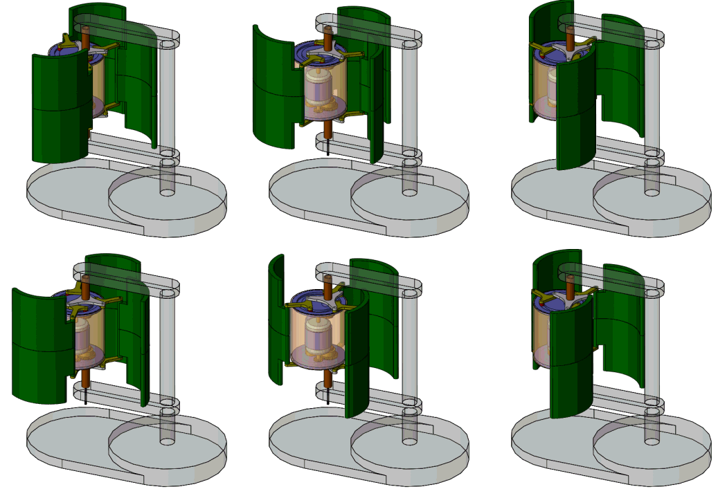
Figure 1 shows a rough concept model that we will use as a starting point.
It is a bit unusual to have a finished model to start with, but it makes it a lot easier for you to follow the modeling process—which is the point of this article.
Each 3-D CAD system has a unique set of “best practices." Because not all of us are using the same software, I’m going to use modeling techniques that are pretty generic. If you prefer to use a layout sketch, blocks in sketches, multibody part files, or some other approach, that’s good.
What I’m going to do is model each component of this gizmo as a separate part in a separate file. Then I’m going to assemble those parts into a working mechanism. From there I’ll hand the model to you, and you can finish it up and take it to market.
The Secret Mechanism
Figure 2 shows a series of stop-action shots overlaid on top of each other for about 20 degrees of rotation. This is an elliptical swing—the blades move at different speeds as they orbit around the hub. It is easier to understand this if you can see it move, but let me describe the main elements of the linkage.
Circular Path. The guiding element is a circular track. Three rollers, shown in red in Figure 2, slide inside the track. These rollers guide one side of the T links in a circular path. The other side of the T link is connected to a trilink that rotates around the hub.
Elliptical Path. The hub is off-center from the track. As the trilink rotates, the long tip of the T link travels in an elliptical path. The relative angle of the T links to the hub changes during this elliptical travel so that the outer tip of the blade is nearer or farther from the stationary hub during its orbit.
When the blade is extended out, it catches more air and rotates in the direction of the red arrow. As the blade moves to the upwind side, it is folded back to present less air resistance.
RPM Governor. Note that the yellow T links and the green blades are rigidly attached to each other. In Figure 2 a pivot point appears to be evident where the blade connects to the T link. I don’t know why I did that, but let’s pretend that it allows us to tune the speed and torque of the installation to match the prevailing wind.
Figure 3 shows the gear train that drives the generator. The linkage to each end of the generator’s shaft is the same. The generator’s shaft is part of what keeps the blades parallel.
Each of the two gray trilinks rotates around a stationary axle tube—shown in brown. A large drive gear is attached to the trilink. The drive gears engage with gears that rotate with the shaft of the generator.
Figure 4 shows the component that holds the generator in place. This same rigid frame attaches to the two track plates so that they don’t twist out of place.The stationary axles referred to in Figure 3 are more clearly shown as being clamped to the generator mount. This rigid assembly is attached to the stand and thus to earth.
Here's the good news about our work: The linkage can be modeled, and the simulation can demonstrate that it rotates without friction. We can make animations that show that this mechanism will move exactly as we need it to in order to capture the breeze.
Here's the bad news: The friction in the system will be greater than the available torque from the blades—at least the way I have it modeled so far.
I certainly don’t know everything about 3-D CAD and related simulation tools. One of the things I don’t know is how to simulate the friction and deflection that this mechanism will exhibit. The most reliable way to prove this doesn’t work is to build it.
Maybe I’m wrong. Maybe this does work and you’re about to become the next Edison! I hope so. I’ll be eager to be your first customer!
The Perpetual Opportunity
This mechanism is a variation on a critter that is sometimes referred to as a perpetual motion machine. That is a term of derision among inventors: It is insulting to be told that you’ve invented such a machine. That’s because they’re really hard to make work. However, they’re really easy to model in frictionless 3-D CAD.
If you read this far hoping to get a tutorial on how to model this project, please send me an e-mail mentioning what you’d like to discuss. Otherwise, this was my little April Fool's prank. Next month we’ll get back to serious CAD jockeying.
Gerald would love to have you send him your comments and questions. You are not alone, and the problems you face often are shared by others. Share the grief, and perhaps we will all share in the joy of finding answers. Please send your questions and comments to dand@thefabricator.com.
About the Author
subscribe now

The Fabricator is North America's leading magazine for the metal forming and fabricating industry. The magazine delivers the news, technical articles, and case histories that enable fabricators to do their jobs more efficiently. The Fabricator has served the industry since 1970.
start your free subscription- Stay connected from anywhere

Easily access valuable industry resources now with full access to the digital edition of The Fabricator.

Easily access valuable industry resources now with full access to the digital edition of The Welder.

Easily access valuable industry resources now with full access to the digital edition of The Tube and Pipe Journal.
- Podcasting
- Podcast:
- The Fabricator Podcast
- Published:
- 04/16/2024
- Running Time:
- 63:29
In this episode of The Fabricator Podcast, Caleb Chamberlain, co-founder and CEO of OSH Cut, discusses his company’s...
- Trending Articles
How to set a press brake backgauge manually

Capturing, recording equipment inspection data for FMEA

Tips for creating sheet metal tubes with perforations

Are two heads better than one in fiber laser cutting?

Hypertherm Associates implements Rapyuta Robotics AMRs in warehouse

- Industry Events
16th Annual Safety Conference
- April 30 - May 1, 2024
- Elgin,
Pipe and Tube Conference
- May 21 - 22, 2024
- Omaha, NE
World-Class Roll Forming Workshop
- June 5 - 6, 2024
- Louisville, KY
Advanced Laser Application Workshop
- June 25 - 27, 2024
- Novi, MI


