


Contributing Writer
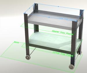
: Figure 1: The design is modeled using several reference planes such as Leg Top, Upper Tray, Lower Tray, and Earth.
From the outset our design project has emphasized parametric modeling techniques. The intent behind this approach is to make it easy to edit the overall size of the assembly. Some of the reference planes we’ve used are shown in Figure 1.
(The usual disclaimer: If you’re not using the same 3-D CAD software as I am, then you’ll have to translate some of the terminology. However, the concept of parametric modeling is widely applicable.)
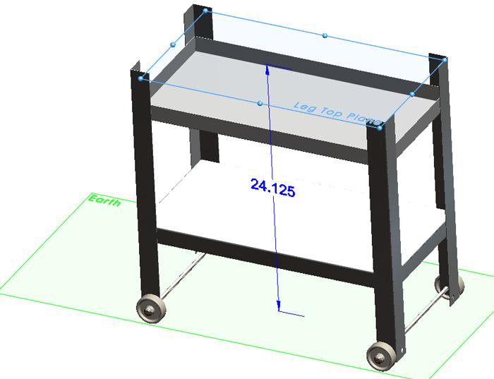
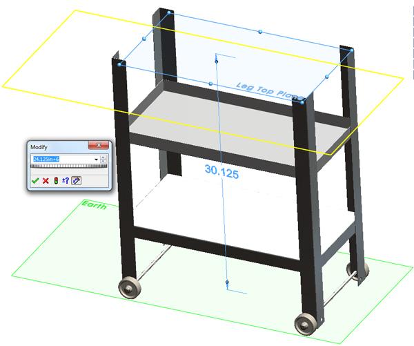
It is a good practice to test parametric links as your design progresses. For example, Figure 2a shows the Top Leg Plane set at 24.125 inches above the Earth Plane. In Figure 2b, that value has been increased by 6 in. It appears that the length of all four legs has changed as we expected. We could leave the legs in this longish state, but I think I’ll set the parameter for the Top Leg Plane back to 24.125 in. for now.
What could possibly go wrong with a parametrically driven model? Lots and lots!
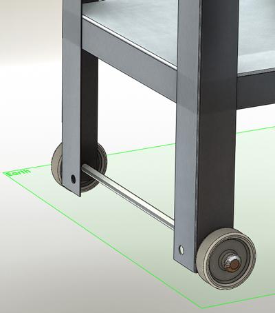
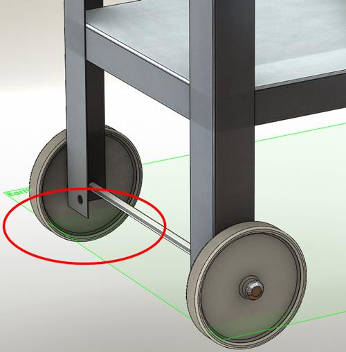
One common problem is illustrated in Figure 3a and Figure 3b. The original intent was to model the assembly with the wheels resting on the Earth Plane as shown in Figure 3a. However, if the wheel size is changed as shown in Figure 3b, it is revealed that the wheels have no positional connection to the Earth Plane. They appear to have sunk into the ground!
What went wrong? When we did the initial planning for the design, it was decided that the Axle Plane would be used to define how far above the earth the axles would be. That made sense at the time because we didn’t consider how the wheels would be obtained. The planning committee’s design intent assumed that the wheels would be parametrically modeled using the Axle Plane and the Earth Plane.
Contrary to the expectation of the initial design intent, the wheels were modeled to match an off-the-shelf catalog item.
Is it a big deal that our wheels are sunk below an imaginary plane? This really doesn’t change the sheet metal design. However, we do plan to generate some marketing images as part of this design project. So, the first option—ignore the problem—isn’t the best course of action.
We are faced with either changing the wheel model to be parametrically driven—our second option—or to change our model to adapt to the fixed wheel size—our third option.
I came up with that “option preference? list by considering the impact on the CAD jockey. In general, getting the project completed quickly is a high priority, but that is seldom the only consideration. Impact on other parts of the project, as well as attention to detail, may compel us to spend more time fixing problems than we’d like.
In this case, the answer has been given by the decision to use off-the-shelf wheels. We are not supposed to design a custom-sized wheel.
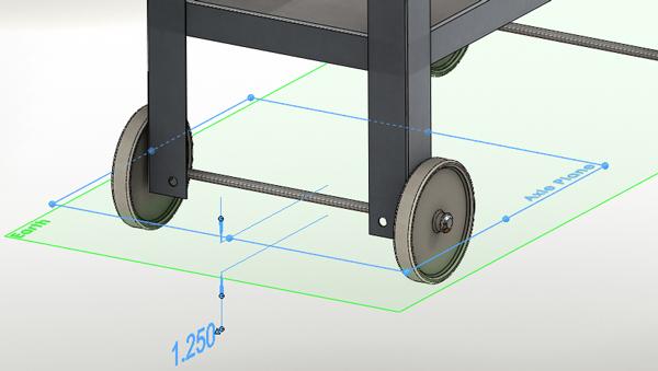
Right now our Axle Plane is modeled at a fixed distance above the earth (see Figure 4). What we need is for it to be defined at the center of rotation of the wheels. And, we need the wheels to rest on the Earth Plane.
The wheel model was created as a revolved solid. Its origin is at the center of its rotation. To redefine the Axle Plane, I’m going to define it as parallel to the Earth Plane at a point; that point is the origin of the wheel.
To make the wheel rest on the earth, I’m going to add a tangent mate between the wheel and the Earth Plane. The lovely result is shown in Figure 5.
We’ve modeled quite a few parts based on the original definition of the Axle and Earth Planes. What are the consequences of changing their definitions?
Fortunately, we modeled the legs relative to the Top Leg Plane and the Axle Plane. Since the Top Leg Plane is defined relative to the Earth Plane, the top of the leg is still 24.125 in. above the earth. Changing the size of the wheel just makes the leg adjust its length—shorter in this case.
The trays also were modeled on planes that were defined at specific distances above the Earth Plane. Changing the size of the wheels will not move where the trays are relative to the top of the legs or to the earth.
If those results satisfy our design intent, then our parametric model has passed its test.
In Part VII of this series, we’ll add some holes for bolts and some details to the top tray to keep the charcoal burning.
Keep in mind that this top-down modeling technique we’re using is not the only way to do this work. It may not even be the best way in every situation. However, when it comes to virtual prototyping, it is efficient to use parametrically driven features. It takes some time to set up initially, but it will pay off later by speeding the revision process. The use of reference geometry to control parametric features reduces the complexity of figuring out what drives what.
Gerald would love to have you send him your comments and questions. You are not alone, and the problems you face often are shared by others. Share the grief, and perhaps we will all share in the joy of finding answers. Please send your questions and comments to dand@thefabricator.com.


The Fabricator is North America's leading magazine for the metal forming and fabricating industry. The magazine delivers the news, technical articles, and case histories that enable fabricators to do their jobs more efficiently. The Fabricator has served the industry since 1970.
start your free subscription
Easily access valuable industry resources now with full access to the digital edition of The Fabricator.

Easily access valuable industry resources now with full access to the digital edition of The Welder.

Easily access valuable industry resources now with full access to the digital edition of The Tube and Pipe Journal.

Easily access valuable industry resources now with full access to the digital edition of The Fabricator en Español.
In this episode of The Fabricator Podcast, Caleb Chamberlain, co-founder and CEO of OSH Cut, discusses his company’s...


