


Contributing Writer
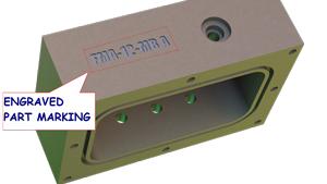
Figure 1a: An example of engraved part marking is shown. Use a font with radius ends or add fillets to a cut-extrude.
During this holiday season as you are building model cars with grandkids, the part numbers on the plastic part trees prove to be helpful when you’re trying to distinguish between components like a shift lever, a piece of scrap, and a windshield wiper.
Part marking is an integral part of many production manufacturing operations. At a minimum, the part number and revision are recorded on the packaging container. The cost of part marking is a function of method and labor. As with any fabrication process, our desire is for lower cost.
Part marking methods include handwriting, ink stamping, screen printing, chemical etching, metal stamping, laser etching, and machined engraving. Which one is the lowest-cost process? That’s a trick question because the answer depends on the project.
The batch quantity of parts to be marked will narrow the choice for the most cost-effective part marking method. For example, marking a one-off custom part would be cost-effective if it were done by hand engraving. By the same token, metal stamping a sheet metal part while it is still in the nested blank adds mere seconds to the overall production time. As a selection consideration, the setup time for CNC stamping makes it impractical for one-offs. Handwriting a part number on thousands of parts is an abuse of labor.
Batch quantity isn’t the only consideration when selecting a part marking method. Some parts present size or shape challenges to part marking.
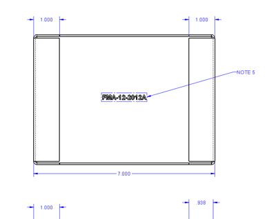
We’re going to limit the scope of this discussion to CNC part marking methods: laser, stamped, or engraved. Examples are shown in Figure 1a and Figure 1b. Further, we’re going to focus on how to specify the part marking for the manufacturing documentation. One method is shown in Figure 2. We’re going to reduce our part marking expense by using a process that minimizes human labor, both at the CAD workstation and at the production line.
As part of the design intent scenario for this article, we are part of a CAD department tasked to include part marking specifications on all items we design for production. We embrace part marking and enjoy the benefits of being able to pick up the item in any context and identify where it belongs, where it came from, or whether or not it is obsolete.
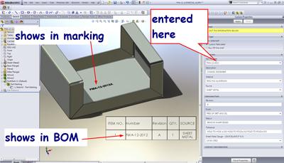
We want to add efficient part marking capability to our CAD modeling skill set. As proficient CAD operators, we want to avoid redundant work. We’ll type the part number and revision in one location in our CAD system (see Figure 3) and have that data apply to the part marking, the bill of materials, and the title block on the manufacturing drawings. Further, when our finished 3-D model is analyzed by the CNC programming system, the part marking will be recognized in the correct location with the desired appearance and text with minimum input from the operator of the CNC programming system.
The CAD technique I recommend is to model the part with all of the detail that you need for manufacturing. That includes marking the part exactly as it is expected in the finished product.
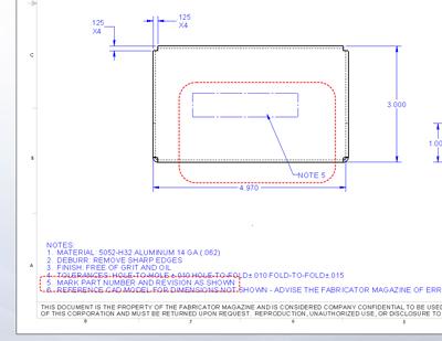
An alternative CAD technique to detailed modeling is simply to put a note on the print that says “MARK THE PART WITH PART # AND REV,” as demonstrated in Figure 2.
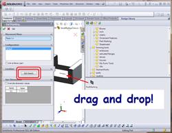
Figure 8: Drag and drop from the library to the part to add 3-D part marking to the part model.
Both approaches have some pros and cons. The latter—just a simple note on the drawing—minimizes the CAD jockey’s effort but puts a large burden on the CNC crew. They have to decide on the font, text size, and text orientation of the marking. There is also the risk that the part marking location and appearance will be very different from batch to batch, possibly even from part to part.
With the recommended technique—adding full detail to the 3-D model—the CAD workstation has to work harder to present all of the tiny facets and faces that result from the part marking detail. An upgrade to a better graphics card in the CAD workstation will address this objection. The benefits of having the CAD jockey expend a little more effort include predictability and consistency in the part marking (see Figure 4).
We now turn to the details of how we are going to set up the CAD workstation so that the part marking specification process is basically drag and drop. What you see is what you get: pain-free CAD operation.
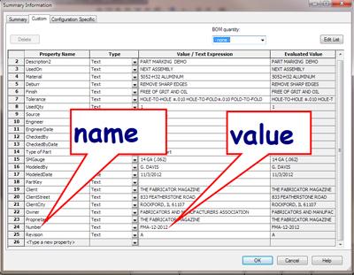
At the lowest level of CAD detail, we are going to embed Custom Properties into the 3-D CAD file for the part that is to be marked. Figure 5 shows a screen shot of the File>Properties form. In our design scenario, we’ll use two Custom Properties—Number and Revision. Those Custom Properties will store the data used for part marking, BOMs, and title blocks.
From previous editions of this column, you may recall the use of templates for creating new parts, assemblies, and drawings. We’ll update our templates to incorporate our new Custom Properties. When updating old projects to include the new part marking work flow, we might use copy and paste to add the required Custom Properties. The Custom Properties just gives us a place to store the information we want to include in our part marking. We also need to model the part marking feature.
We are going to model our part marking in 3-D in the sheet metal part by making a cut-extrude. The sketch for that cut-extrude will be linked to the text stored in the Custom Properties.
To avoid having to redraw the sketch, relink to text, and re-create the cut-extrude for every part we model, we’re going to create a Library Feature. That will let us simply drag and drop the part marking feature onto our sheet metal model and add a dimension or two for locating.
Presto! Part marking is modeled with minimum fuss.
We’ve discussed how to make cut-extrudes, edit Custom Properties, and define BOM templates and Drawing Template setup in previous articles. Let’s turn our attention to the topic of Library Features.
Library Features are cool because of their drag-and-drop convenience. However, what you drop may behave badly unless it was originally created with drag and drop in mind. My basic CAD tip when designing Library Features is to avoid having any nonvital sketch constraints.
Completely unconstrained is contrary to my recommendation for all other forms of CAD modeling; that is, 2-D sketches should always be fully defined. Not to worry! We will want to constrain the part marking sketch fully once the drag and drop is complete. We’re considering only the unconstrained route for the purposes of creating that which will be the target of drag.
Not only are the sketches for Library Features unusual, the Library Feature we are creating simply results in a cut-extrude. It does not include the part to cut.
So, how do you save a cut that goes into nothing?
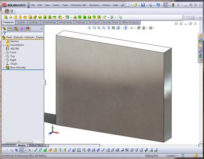
To create our part marking cut-extrude we are going to create a “practice” part (see Figure 6a). The size and shape is arbitrary but needs to be bigger than our part marking. We’ll model the part marking cutting into this practice part. That will give us a cut-extrude that we can add to our library. Once it is in the library, we can discard the practice part.
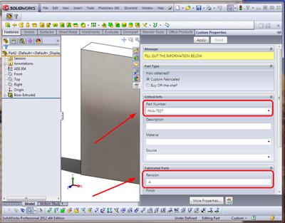
In Figure 6b we use our Custom Properties form to add a value for the part number and revision. Again, these properties are being added to our practice part and will be useful only while we set up our Library Feature, so don’t spend time filling out the rest of the form.
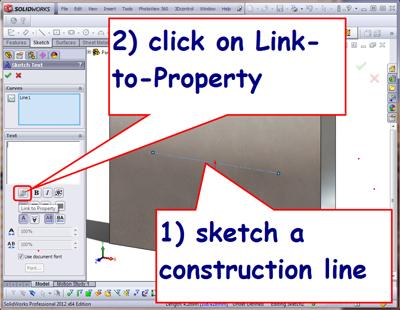
To get to Figure 6c, we selected a face on our practice part and launched the Cut-Extrude tool. We then sketch a construction line. The construction line is useful for locating the sketched text. Avoid sketch relations like “horizontal” or “vertical.” You can use the CTRL key while sketching the line to prevent automatic sketch relations from being created. If they do creep into the sketch, delete them. The length of the line is arbitrary, but it needs to be longer than the part marking text.
With the construction line selected, click on the Text tool in the Sketch Menu. You should now see something that resembles Figure 6c.
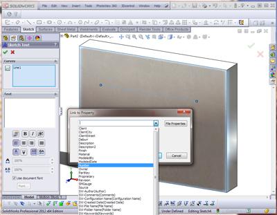
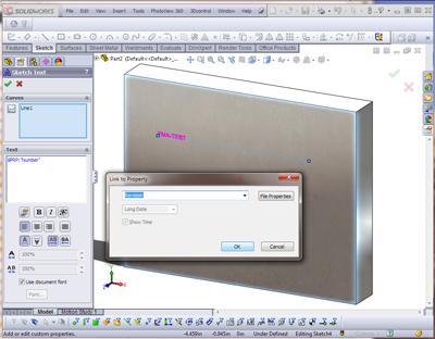
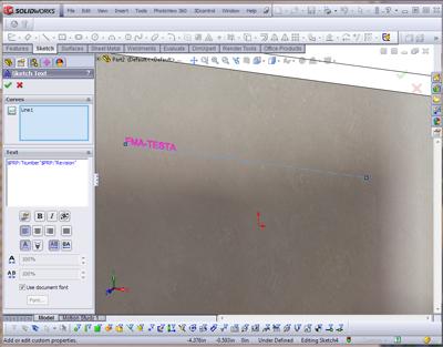
As indicated in Figure 6c, click on the Link-to-Property button. Figure 6d shows the resulting pop-up dialogue that presents a drop-down list. This drop-down list will allow you to select an existing Custom Property by its name. The value stored in that Custom Property will be displayed as text in our cut-extrude. For our demonstration scenario, we want to select the Number property and then click on OK. To add the revision after the part number, click on the Link-to-Property button again and select the Revision property as shown in Figure 6e. After clicking on OK, you should see $PRP:”Number”$PRP:”Revision” in the text block. The graphics window will show a preview of the part marking. In Figure 6f we see “FMA-TESTA” as the preview. That is because of the values entered back in Figure 6b. If a space between the part number and the revision letter needs to be added, the CAD jockey could add it in Figure 6f by putting a space between “Number” and $PRP:”Revision.”
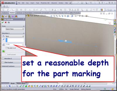
We have successfully sketched our linked text for the part marking. When we exit the sketch for the cut-extrude, we will enter a value for the depth of the part marking. For this demo, we’ll use 0.001 in. for the depth of the cut-extrude (see Figure 6g).
After completing the cut-extrude feature, you should rename it from Cut-Extrude1 to PartMarking.
Our setup for the creation of a Library Feature is nearly complete. To review, we created a cut-extrude. The sketch for the cut-extrude has sketched text that is linked to Custom Properties. There are no other sketch relations or external links in the sketch other than the fact that our sketch plane is a face on our practice part.
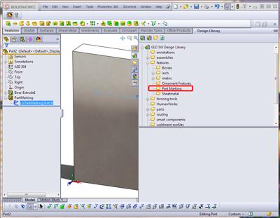
We are now going to drag and drop that cut-extrude into our Design Library. Figure 7a shows that I have created a subfolder named Part Marking that is a child of the Features folder. You can create this folder in the default Design Library, but you should make a copy of the library. This will prevent version upgrades from overwriting your custom library features.
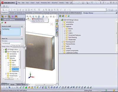
Figure 7b shows the result of dragging the cut-extrude, named PartMarking, from the Feature Manager into the Part Marking folder in the Design Library. Note that the right-hand flyout task pane must be “pinned” to remain visible before you start the drag and drop to add the cut-extrude to the library.
The file name you enter—PartMarking—is the name of the Library Feature file that holds the part marking cut-extrude. You actually can give it any name that makes sense to you.
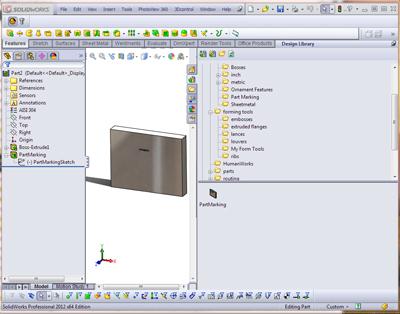
After dismissing the Add to Library Manager, the PartMarking feature should appear in the Design Library. The PartMarking feature in the Feature Manager of our practice part should have an L in its icon to indicate it was created as a Library Feature (see Figure 7c).
We now can close and delete our practice part file.
To test our part marking functionality, open a model that you’d like to add part marking to. Drag and drop the part marking feature onto a surface of the model. That’s all it takes to add the part marking to the part (see Figure 8). You will need to create the Custom Properties—Number and Revision—as well as enter values. FMA-1234 for Number and B for Revision might work, perhaps.
Yes, it took a bit of effort to set up the Library Feature. But once it is ready to use, anyone in your CAD shop can now quickly drag and drop part marking into place.
Gerald would love to have you send him your comments and questions. You are not alone, and the problems you face often are shared by others. Share the grief, and perhaps we will all share in the joy of finding answers. Please send your questions and comments to dand@thefabricator.com.


The Fabricator is North America's leading magazine for the metal forming and fabricating industry. The magazine delivers the news, technical articles, and case histories that enable fabricators to do their jobs more efficiently. The Fabricator has served the industry since 1970.
start your free subscription
Easily access valuable industry resources now with full access to the digital edition of The Fabricator.

Easily access valuable industry resources now with full access to the digital edition of The Welder.

Easily access valuable industry resources now with full access to the digital edition of The Tube and Pipe Journal.

Easily access valuable industry resources now with full access to the digital edition of The Fabricator en Español.
In this episode of The Fabricator Podcast, Caleb Chamberlain, co-founder and CEO of OSH Cut, discusses his company’s...


