


Contributing Writer
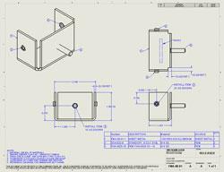
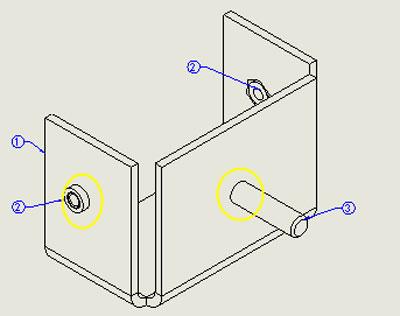
Figure 1a: This 2-D drawing was generated by the software from a 3-D part.
We start with the usual disclaimer that we’re examining functionality that is unique to SolidWorks®. In this article we discuss some of the challenges associated with top-down modeling as it relates to the manufacturing of sheet metal products using 3-D CAD models.
The drawing shown in Figure 1a has arrived in our inbox. Figure 1b highlights the isometric view that the 3-D CAD system generated. Something is not right about this view: Lines are missing. Figure 1c is a preview of the corrected drawing with the missing lines revealed where the hardware penetrates the sheet metal’s surface.
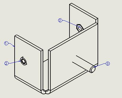
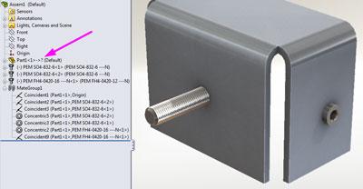
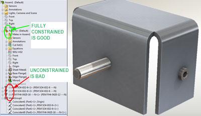
To investigate why the lines are missing in Figure 1b, we open the 3-D assembly (see Figure 2) that the 2-D drawing is referencing. The preview of the 3-D assembly in the Graphics Window looks pretty much as we expect—a sheet metal part and three captive fasteners. As we glance at the Feature Manager, we see that Part1 has some features that are currently out of context; that’s what the ? means in the Feature Manager’s listing for Part<1>->. Out-of-context features are not the cause of the missing lines in the isometric view. However, let’s pause to consider the importance of that ->? in the listing.
Out-of-context features are undesirable once the product has arrived in manufacturing. It is a best-practice habit for CAD operators to avoid things that were once expected to update automatically and no longer do. Either eliminate the expectation or re-establish an unbroken chain of external links.
When this example assembly was originally created, it existed as part of a larger top-level assembly (see Figure 3). In this top-level assembly, we see that various components were used to locate the fasteners in the bracket. We are now supposed to fabricate the bracket—Part1.sldprt. Unfortunately, we don’t have access to the top-level assembly shown in Figure 3. That is why features in our sheet metal bracket are currently out of context. If we could open that missing top-level assembly, the features in Part1 would no longer have ? issues.
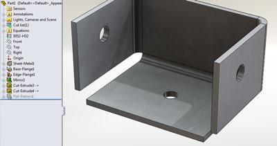
While the dangling external context is a nuisance, that is not what is causing the problem with the isometric view back in Figure 1b. Let’s open the sheet metal part, shown in Figure 4. It has all of the bends but none of the holes for the captive fasteners. The absence of holes is why the lines are missing in Figure 1b; the holes have no edges to show.
Perhaps during the product development phase for this project the design intent was to guarantee that the captive fasteners would align with their mating parts. That was accomplished by mating the fasteners to other components in the top-level assembly instead of by mating the fasteners to holes in the sheet metal in a lower-level assembly.
We are role-playing here, of course. In this scenario, our role is limited to manufacturing. The only 3-D CAD assembly we have access to is damaged goods. We have the responsibility to comply with our scenario’s CAD administration policy. That policy dictates that we add the missing lines to the isometric view. We also are going to eliminate the dangling external links.
We need to cover one other detail in our scenario. We are going to assume that the locations of the fasteners are correct even though they are “floating.” After we open the assembly, we accidentally could move the fasteners out of their correct location. After we’re done with our repair work, it will be more difficult to alter the model accidentally.
Our scenario allows us to develop the part with one set of modeling techniques that are appropriate and streamlined for product development. We adjust our design intent and modeling techniques when we enter the manufacturing stage. As we repair this model, our new design intent is to eliminate all parametric references to other assemblies.
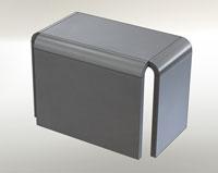
Figure 4: As we dig deeper into the mystery, we see that the sheet metal part does not have holes modeled for mounting the captive hardware.
While a fully parametric model that has external links to ensure proper alignment of holes and components is great during product development, it can lead to accidental or uncontrolled revision initiation in a manufacturing setting. As a result, it is recommended that you lock, break, or remove external links from manufactured designs.
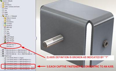
In Figure 5 we are studying the lower-level assembly containing just the sheet metal bracket and the captive fasteners. We want to understand how the captive fasteners were located originally before we jump into improving things.
We discover in Figure 5 that the captive fasteners are mated concentrically with axes that were defined in the context of an assembly that we no longer have. If we deleted those two axes, then we would solve the problem of the dangling external links. However, we still need a way to locate the captive fasteners in a reliable manner—one that is clearly defined and editable.
Two roughly equivalent techniques come to mind:
Without delving into the topic of design intent, it is difficult to say which technique is better. The latter technique is slightly less well trod, so I think I’ll use it for the role-playing scenario we’re engaged in.
Deleting the two dangling axes is simply a matter of opening the part—Part1.sldprt—and deleting each axis from the Feature Manager’s history list.
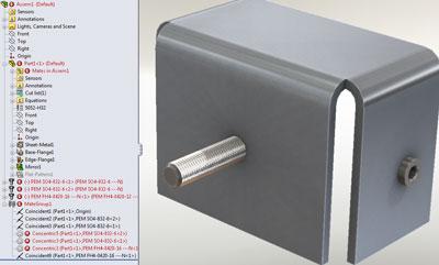
When we return to the assembly—Assem1. sldasm—we see red as shown in Figure 6a. Three concentric mates are now broken. The CAD software shows them in an alarming color to let us know that a problem exists. Our solution in this scenario is simply to delete the mates that are highlighted in red.
The consequence of deleting the broken concentric mates is shown in Figure 6b. We note that the sheet metal part is fully constrained in 3-D space, which is accomplished with a mate at the origin. We also note that the three captive fasteners are floating in 3-D space. That is indicated by the hyphen in front of their names.
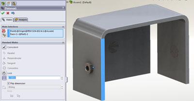
Let’s add mates in Assem1.sldasm to fully constrain the captive fasteners in their proper locations. We do that by mating their origins at the appropriate distance from surfaces in Part1. We know what those distances should be by referring back to Figure 1a.
In Figure 6c we see the progress of adding a distance mate between the center (origin) of the standoff and the edge of the sheet metal bracket. This is repeated for the XY locations of all three captive fasteners.
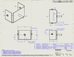
Figure 9: Our corrected drawing has a good isometric view. In this REV B drawing, the dimensions for locating the hardware still match the REV A drawing.
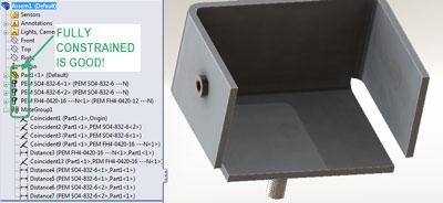
Because their heads were mated as coincident with the surfaces of the sheet metal part, the captive fasteners are constrained fully, as shown in Figure 6d. We know the fasteners are constrained fully because their names have no indicators before them. If we need to change the location of the captive fasteners in the future, it will be done by editing the distance mates that we just added to this assembly— Assem1.sldasm.
Now we need to model the holes for the captive fasteners. We will do that by creating cut-extrudes in the sheet metal part, Part1.sldprt (in the context of the assembly, Assem1.sldasm). That just means that we edit the part while looking at the assembly.
Figure 7 shows progress in sketching a hole to align with the captive stud. Sketching and extrude-cutting are repeated for the other captive fasteners. For the two concentric standoffs, a single cut that went through all of the sheet metal part was made.
Figure 8a shows our final production assembly. This assembly model no longer references the missing top-level assembly. All in-context references are fully resolved. We know this by the -> indicator that follows the feature name in the Feature Manager. Figure 8b shows our final sheet metal part with its new holes for the captive fasteners.
Our corrected Revision B for the part is shown in Figure 9. Our CAD administration policy requires that we send copies of this altered model to the R&D department so that their concept model can be updated with our new assembly. We don’t want to have to repeat this fix next time this part is released to production.
Gerald would love to have you send him your comments and questions. You are not alone, and the problems you face often are shared by others. Share the grief, and perhaps we will all share in the joy of finding answers. Please send your questions and comments to dand@thefabricator.com.


The Fabricator is North America's leading magazine for the metal forming and fabricating industry. The magazine delivers the news, technical articles, and case histories that enable fabricators to do their jobs more efficiently. The Fabricator has served the industry since 1970.
start your free subscription
Easily access valuable industry resources now with full access to the digital edition of The Fabricator.

Easily access valuable industry resources now with full access to the digital edition of The Welder.

Easily access valuable industry resources now with full access to the digital edition of The Tube and Pipe Journal.

Easily access valuable industry resources now with full access to the digital edition of The Fabricator en Español.
In this episode of The Fabricator Podcast, Caleb Chamberlain, co-founder and CEO of OSH Cut, discusses his company’s...


