


Contributing Writer
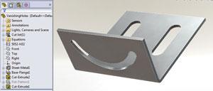
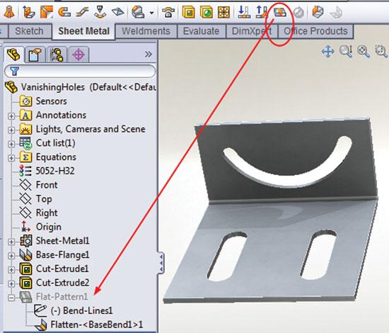
Figure 1: In this example, a sheet metal part has cutouts in both flanges. The modeling history is displayed in the list to the left of the part. Entries in that list can be reordered by dragging them into a different position in the history.
We start with the usual disclaimer that we’re examining functionality that is unique to SolidWorks®. In this article we discuss some of the opportunities of history-based modeling as it relates to the automatic unfolding of sheet metal models.
Consider a scenario that puts us in the role of generating a flat-pattern file for importing into a CNC programming system. This process is essentially two operations—creating the flat layout and creating the file that contains the flat-layout information. The modeling software I use will unfold a properly modeled part automatically. It also will export 2-D data in several formats, including the popular DXF file format.
Although the production of flat layouts is frequently beyond the area of responsibility for 3-D CAD modeling professionals, those modelers should take steps to ensure the manufacturing process is a seamless integration that avoids duplication of effort. Be kind to your CNC programmer! Whenever practical, model using a material thickness, K-factor, and bend radius that your manufacturing team approves. If in doubt, a simple e-mail will get you the information. Given the right settings, the generated flat will be exact.
Several Internet resources provide excellent information about flat layouts. The Web site www.sheet metalguy.com should serve as an inspiration for additional Web searches. His method of flat-layout calculation is not the only one that works.
Back to our scenario. Our customers love the convenience of just sending 3-D CAD models to us and leaving all of the drafting in our hands. Our hypothetical service transfers a lot of responsibility to us, so we must always be cautious about making changes to the 3-D model. Don’t inject edited models into a manufacturing process without permission. Make sure you keep original copies safe and secure for reference. Confer with the originating designers to make sure you are not creating a monster with your good intentions.
Outside of the CAD world, making a flat layout consists of calculated plotting and verification of the calculated plot. The verification of the flat layout—using the specifications for the finished part as the controlling document—is vital to success. The “specifications” are traditionally delivered as drawings printed on sheets of paper with projected views in accordance with industry standards.
The most labor-intensive solution for the production of the flat layout is to redraw an appropriate 2-D profile manually based on the projected views while using the correct bend compensation for proper sizing. A less labor-intensive solution is to have the 3-D CAD editor export a perfect 2-D flat layout for the part in question. I’m a fan of efficiency, so let’s use the automatic approach.
No matter how the flat layout is produced, it needs to be checked against the original specification to eliminate errors and omissions. The primary advantage of the CAD-generated flats is that proofreading someone else’s work—in this case, the computer’s—can have a higher success rate than double-checking your own lengthy list of tedious math and mental interpretation of a 2-D drawing of a 3-D part. Which begs the question, “What could possibly go wrong with computer-generated flat patterns?”
In Figure 1 a 3-D CAD model for a bracket that we’ve inherited is shown. The goal is to make a flat pattern for CNC production. The CNC programming department has requested that the flat layout be delivered to them in a DXF file format.
Let’s study the process of exporting the flat pattern for the part shown in Figure 1. In Figure 2a, you’ll note that the Flat-Pattern1 feature is highlighted in the Feature Manager’s history list. The first step in exporting a flat-pattern DXF file is to right-click your mouse on the Flat-Pattern1 feature.
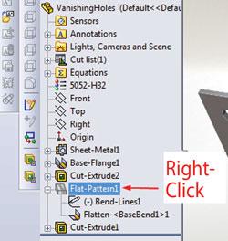
Figure 2a: To start the DXF export process, right-click on Flat-Pattern1.
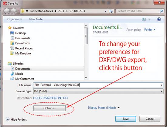
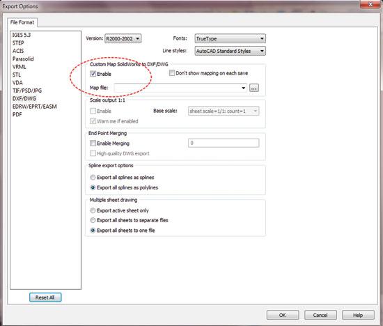
From the pop-up menu, select Export to DXF/DWG to launch a dialog similar to that shown in Figure 2b . Click on the Options button to get to Export Options dialog shown in Figure 2c .
To complete the Export Options dialog options properly, you need information about the target system—the software that will be importing the DXF file. You might run a few test cases with various options to verify that no versioning conflict between 3-D CAD and 2-D CNC prep exists. I’m not going to cover all of the options here, but I recommend that you read the information found in the Help system to learn about settings that are useful for exporting DWGs to other CAD systems.
Referring to the Export Options dialog box in Figure 2c,
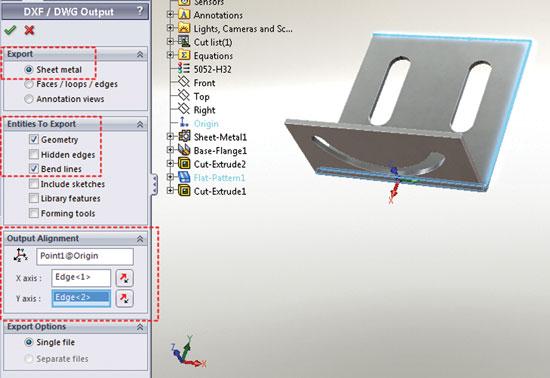
After saving or canceling this review of export preferences, let’s go back to Figure 2b. It’s time to give the exported DXF a meaningful file name and click on the Save button. That leads to Figure 2d —the DXF/DWG Output dialog.
Here’s a review of some of the settings in the DXF/DWG Output dialog:
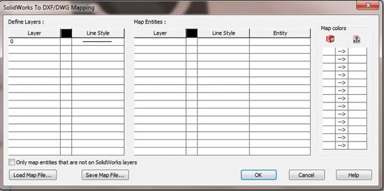
After clicking on the Green Checkmark to accept the displayed settings in the DXF/DWG Output dialog, a DXF/DWG Mapping dialog, as shown in Figure 2e, is next.
The SolidWorks to DXF/DWG Mapping dialog allows you to define layers, map entities, and map colors so that the result in the target system more closely matches the appearance as viewed with SolidWorks. You might be tempted strongly to disable the mapping options when generating flat DXFs, which is certainly my habit. However, I wanted to drag you through all of these options so you might discover that magic option that simplifies your workflow, particularly when exporting drawings to other 2-D CAD editors.
In the case of a flat layout, a CAD jockey doesn’t have much to map in the way of layers and line types, so click on OK. This will launch the DXF/DWG Cleanup tool.
“Dirty” DXFs have lines on top of lines, dashed lines around hardware holes, and other sketch entities that merely confuse the CNC programming effort. This Cleanup tool does a fine job of prepping the flat pattern for generating a tidy DXF.
Figure 2f shows an example of the DXF/DWG Cleanup tool. This is a preview of what the exported DXF will include. You’ll recall that I included Bend lines in my output options (see Figure 2d). To remove a bend line—or any other sketch entity—select and then click on the Remove Entities button. Repeat until satisfied. Then, with a mouse click on Save, SolidWorks will proceed with the creation of a DXF file containing a 2-D flat layout of the sheet metal part.
As a side note, a different technique for creating DXF flats is available. That process involves creating a drawing—a slddrw file type—that includes a flat view of the part and then saving that drawing as a DXF. The slddrw could include layers, colors, and line types that are not available in the direct flat-DXF export technique.
And, as a bit of reassurance, generating a flat-pattern DXF is not very hard. The default settings usually work just fine.
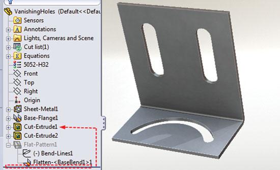
At the end of the export process, my vanishing demo part gets rebuilt. The result is shown in Figure 3. The disappearance of the slots is not a flaw in the software, but rather is a result of the modeling technique that was used to create this demo part.
Note in Figure 3 that Cut-Extrude1 is a child of Flat-Pattern1. It appears after Flat-Pattern1 and has some feature that is associated with Flat-Pattern1. By default, all children of a parent will follow the suppression of the parent.
The DXF flat-pattern export process, in order to flatten the part, unsuppressed Flat-Pattern1. As a consequence, its child Cut-Extrude1 also was unsuppressed. That had no apparent impact on the slots in Cut-Extrude1 because they started out in an unsuppressed state. As the export process completed, it returned the Flat-Pattern1 feature to the suppressed state. As a consequence, the Cut-Extrude1 also was suppressed. That’s why the slots appeared to disappear in the model.
Finding Fault With Fixing Flats
What to do about this weird model depends on your area of responsibility. It is conceivable that you’ve created the flat-pattern DXF file and that’s enough. The fact that the slots are vulnerable to unexpected suppression might not be something you need to correct.
Suppose, however, that you’re also responsible for creating the shop drawings for the part. That means that at least you need to get the slots back into an unsuppressed state. Let’s go all the way and suppose that you have authority and responsibility to correct the model so it doesn’t have vanishing holes.
The first step is to consider why Cut-Extrude1 was modeled as a child of Flat-Pattern1. Somebody might have a rational reason why a feature—like a cutout—would be expected only in a flat configuration of a part. We could speculate on reasons why various configurations of a model would include or exclude features. Instead, let’s presume that Cut-Extrude1 should not be a child of the Flat-Pattern1.
In this bad demo model, we’re lucky. All we have to do is click-and-drag Cut-Extrude1 up the history list so that it appears anywhere prior to Flat-Pattern1. Right after Base-Flange1 might make sense. In a more complicated example, a CAD operator might have to delete some sketch relations to reorder the feature in the Feature Manager’s history list.
The names of these features were generated automatically as I created them. This gives you a strong hint about how I created this bad example. In the real world, this problem under discussion might be a consequence of an accidental dragging with the mouse.
Even though the reordering of features in the Feature Manager’s history list appears to have succeeded, the slots won’t reappear until Cut-Extrude1 is unsuppressed as shown in Figure 4 .
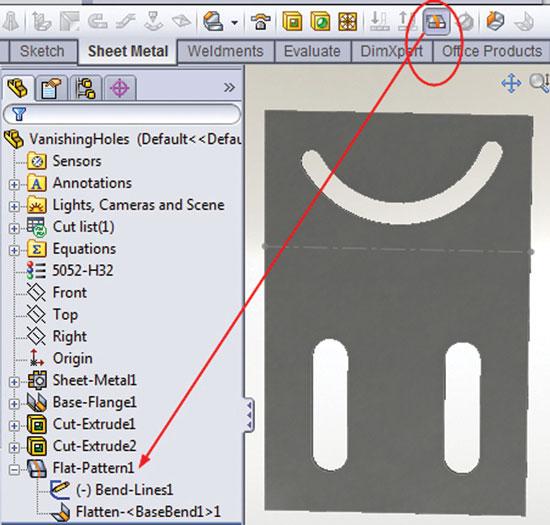
As a test of the repair, we click on the Flatten icon (see Figure 5a ). The part unfolds because the processing of bends is unsuppressed, and all the holes are shown as expected. Figure 5b shows the unclicked Flatten icon with the part folded and all the holes. The part appears to be folded because the processing required to unfold the part is suppressed.
Now that the part is modeled so the cutouts persist regardless of the flat/folded configuration of the part, it’s possible to proceed in making the shop drawing without problem as shown in Figure 6. Note that the figure includes both a flat pattern and a formed part as demonstration that the “correction” made to the model was the right thing to do.
Gerald would love to have you send him your comments and questions. You are not alone, and the problems you face often are shared by others. Share the grief, and perhaps we will all share in the joy of finding answers. Please send your questions and comments to dand@thefabricator.com.


The Fabricator is North America's leading magazine for the metal forming and fabricating industry. The magazine delivers the news, technical articles, and case histories that enable fabricators to do their jobs more efficiently. The Fabricator has served the industry since 1970.
start your free subscription
Easily access valuable industry resources now with full access to the digital edition of The Fabricator.

Easily access valuable industry resources now with full access to the digital edition of The Welder.

Easily access valuable industry resources now with full access to the digital edition of The Tube and Pipe Journal.

Easily access valuable industry resources now with full access to the digital edition of The Fabricator en Español.
In this episode of The Fabricator Podcast, Caleb Chamberlain, co-founder and CEO of OSH Cut, discusses his company’s...


