


Characteristics of electron beam welding
Process is suitable for fabricating structures, difficult steel and aluminum applications
 |
| Figure 1 EBW is suitable for manufacturing spherical aluminum tanks. |
Editor's Note: This article was adapted from "State-of-the-art and advanced technologies of electron beam welding of structures," which appeared in the November 2004 issue of The Paton Welding Journal. The research for this article came from several sources; for a complete list of the sources, please contact the authors.
Electron beam welding (EBW) is used mainly for fabricating structures that have stringent quality, strength, and joint reliability requirements. For more than 45 years this process has been applied in aerospace, shipbuilding, and instrument manufacturing.
The E.O. Paton Electric Welding Institute (PWI) developed and introduced this technology for industrial fabrication of large casing structures and fuel tanks for ballistic missiles, naval missiles, and cruise missiles. EBW also is useful for welding foil systems for hydrofoils; as a final assembly-welding operation for fabricating launch platform gyroscopes; and manufacturing modern tanks and ship navigation systems. EBW is used to make thick-walled shell structures of nuclear complexes and thin-walled elements of microwave devices.
EBW of aluminum alloys is widely applied in fabricating structures that have strict strength and joint tightness requirements and must withstand rigorous operating conditions such as alternating loads, deep vacuum, and cryogenic temperatures (see Figure 1). EBW is cost-effective for many mass production applications, such as welding pistons that have an oil-cooling cavity, which are used in augmented diesel engines (see Figure 2). It is useful as a finishing operation, such as welding cases and gyroscope floats.
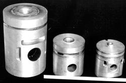 |
| Figure 2 EBW is useful for hardfacing. A typical application is the hardfacing in the upper compression groove of these pistons. |
This process is particularly effective in fabricating large structures that have a single type of welded joint. In this type of application, the process relies on local vacuumizing of the butt joint before welding. Examples are large-diameter shells that having several longitudinal butt joints, as well as thick-walled aluminum panels for bottom blanks for railway tank cars. The technology also has been used to make shells of sheet finned panels that require welding elements with elastic pretension.
Why Choose EBW?
PWI has developed several guidelines about the characteristics and uses of EBW. Compared with arc welding processes, EBW improves joint strength 15 percent to 25 percent. It has a narrow heat-affected zone (HAZ), which results in lighter-weight products. Geometric shapes and dimensions are highly stable, particularly when it is used as a finish operation. It eliminates oxide and tungsten inclusions and removes impurities. The weld metal has a fine crystalline structure.
EBW also is suitable for a variety of difficult applications, such as welding structures on which the reverse side of the butt is inaccessible; gravity welding of thin metal; and welding in various spatial positions. It allows feeding of filler wire into the weld pool; provides a low level of overall heating of the structures; and has the ability to vacuumize the inner volume simultaneously, which is suitable for sealing instruments. Because EBW is an automated process, the welded joint quality is consistent. The process does not require shielding gases, tungsten electrodes, or edge preparation for welding thick metal. Finally, it can be used to weld some joints that cannot be made by other welding processes.
 |
| Figure 3 Operator control of the electron beam allows customizing the spatial distribution of the beam's power density. The numbers indicate the relative beam dwell time at the various points along the scanning contour. |
New structural materials with unique properties are available. For example, aluminum-lithium alloys, aluminum matrix composites, aluminum foam, and nanomaterials are used widely in the aircraft, aerospace, and defense industries. Likewise, EBW technologies, equipment, and controls improve continuously. PWI developed a fundamentally new EBW technology that facilitates controlled heat mass transfer of a formed volume of weld pool liquid metal.
EBW Implementation and Application
The basis of the new process is an instrument that controls the electron beam—a programmer provides discrete scanning of the electron beam on any assigned trajectory and allows the beam to be stopped at any point on the trajectory with controlled dwell time. The programmer is compatible with any power source made by any manufacturer.
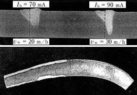 |
| Figure 4 Transverse macrosections of asymmetrical penetration of AMg6 alloy show the penetration depth at two current levels—70 milliamps (left) and 90 milliamps (right). |
Controlling the beam power distribution in the heated spot enables:
- Controlling the fine structure of the weld metal and therefore improving the mechanical properties of joints.
- Avoiding the anisotropy of strength characteristics in butt joints with thick edges.
- Producing joints that have uniform weld width across the edge thickness, thus reducing residual angular deformations.
- Welding joints with a large gap in the butt without electron beam penetration into the gap.
- Welding dissimilar materials that have different thermophysical characteristics, which is facilitated by providing two different heat inputs along the butt edges.
- Joining materials of differing thicknesses (the ratio can exceed 1-to-50).
- Performing butt welding with simultaneous feed of filler wire from any side of the weld pool relative to the direction of beam displacement.
- Welding joints with incomplete penetration without forming root defects.
- In circumferential welding, to avoid formation of defects in sections where the crater fades out and welds overlap.
- Modifying alloying surface layers of parts without diluting the matrix material.
 |
| Figure 5 In melting a previously deposited filler metal, three variations on the scanning frequency and focal spot position result in three distinctly different surface layer formations. |
Beam displacement sequences and power density distribution are shown inFigure 3. The welding equipment operator develops the program for making a specific joint using the necessary parameters—including path shape, number of points, sequence of beam displacement from point to point, scanning amplitude, and beam dwell time at each point.
Asymmetric penetration of AMg6 is shown inFigure 4. Changing the beam displacement parameters results in variations in the weld metal structure formation (seeFigure 5).
Joining Difficult-to-weld Metals and Dissimilar Metals
PWI has used EBW for welding advanced materials that are difficult to weld or are thought to be unweldable. One application is high-strength aluminum-lithium alloys (see Figure 6). These alloys have higher strength properties compared with the widely used AMg6 and 1201 alloys and reduce the welded structure weight by 15 percent to 20 percent.
EBW resolved the problem of welding tubular transition pieces of dissimilar materials, namely, stainless steel to aluminum alloys, for cryogenic engineering. Conventional methods that do not melt the edges—explosion welding, metallurgical rolling of the bimetal, or diffusion welding—often are used to make such transition pieces. These traditional processes result in joints that have pure aluminum in contact with steel. Such a joint has the strength properties of pure aluminum, but its performance under thermal cycles is limited due to the intermetallic interlayer in the transition zone.
PWI developed a method that does not result in direct contact between aluminum and steel. A 3- to 7-mm layer of modifiers such as nickel, zirconium, or niobium is applied from the vapor phase in the vacuum chamber onto the surface of the stainless pipe to be welded. A specific temperature mode ensures the deposited layer adheres to the steel. Then, after assembly of the stainless steel pipe with that of any aluminum alloy, butt welding is performed to penetrate the aluminum pipe to the entire thickness, while the edge from the steel side is just preheated and wetted with liquid aluminum. The ability to program the heat input in the required volume into each of the billets makes this process possible. Modifiers on the steel pipe surface provide additional alloying of the aluminum pool melt, and the joint acquires new properties. Rupture testing reveals that the ultimate strength is 320 to 350 megapascals (MPa), which is four to five times higher than in joints that have a layer of intermetallics and pure aluminum.
 |
| Figure 6 Aluminum-Lithium Alloys' Welded Joint Strength Properties |
Another application is Al-matrix composites strengthened by SiC and Al2O3 particles without melting the edges. Such joints are welded by applying to the edges a dispersed flow of fine drops of filler material. Both the composite-matrix material and another aluminum alloy can be used as the filler material. The consumable electrode of filler material is surface-melted by the electron beam, and because of its high-velocity rotation, the finest drops form a joint without defects or interfaces.
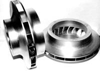 |
| Figure 7 EBW is suitable for fabricating high-strength stainless steel impellers for a centrifugal compressor. |
In EBW of structures with thick edges or with varying cross sections, a technology has been successfully implemented that provides microalloying of weld metal with modifiers such as scandium or zirconium across the entire depth of the pool. A filler in the form of foil, 100 to 200 mm thick, is placed into the joint before welding. The foil is produced by superfast solidification in a vacuum (up to 107 K/s) and includes modifiers in amounts that are higher than their mutual solubility in aluminum. For instance, scandium content is 2 to 4 volume percent, and zirconium is 1.4 to 1.5 volume percent. This increases the joint tightness and, more important, improves the strength properties of joints of any grades of aluminum alloys and hot cracking resistance.
In manufacturing high-strength stainless steel impellers (see Figure 7) for centrifugal compressors, the cover disk is fastened by a slot electron beam weld to the integral blades of the main disk. Then sections that lack penetration are filled with a high-temperature braze alloy and vacuum brazed. The joint strength is equivalent to base metal at fatigue and in long-term strength testing.
B.E. Paton and A.A. Bondarev are research scientists at the E.O. Paton Electric Welding Institute, 11, Bozhenko Street, Kiev 03680, Ukraine, 380-44-261-5045, fax 380-44-268-0486, paton@paton.kiev.ua, www.paton.kiev.ua.
About the Authors
About the Publication
subscribe now

The Fabricator is North America's leading magazine for the metal forming and fabricating industry. The magazine delivers the news, technical articles, and case histories that enable fabricators to do their jobs more efficiently. The Fabricator has served the industry since 1970.
start your free subscription- Stay connected from anywhere

Easily access valuable industry resources now with full access to the digital edition of The Fabricator.

Easily access valuable industry resources now with full access to the digital edition of The Welder.

Easily access valuable industry resources now with full access to the digital edition of The Tube and Pipe Journal.

Easily access valuable industry resources now with full access to the digital edition of The Fabricator en Español.
- Podcasting

In this episode of The Fabricator Podcast, Caleb Chamberlain, co-founder and CEO of OSH Cut, discusses his company’s...


