


Drawing the bead on weldments
A close look at top-down modeling using a specialized 3-D CAD modeling tool
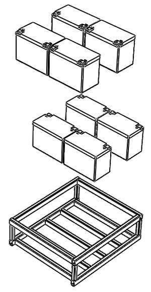
Figure 1Here is an exploded view of what we have in mind for a battery cage.
?Our project this month is to model a cage that will hold about 528 pounds (240 kg) of batteries. Our project manager has not settled on the specific battery spacing or on the structural members to use, so a major element of our design intent it to make it easy to change the size as well as the materials used in the cage. Figure 1 shows an exploded view of a starting concept.
The Hard Part of the Easy Way
It is possible to model each of the "sticks" in the cage as separate parts. It could be done with extruded profiles or with sweeps. However, with the 3-D CAD software I'm using, that would be the hardest way to model this project.
The easier method is to use a collection of tools titled Weldments. The basic process has four steps:- First, use a 3-D wireframe sketch to define the paths of the structural members of the weldment—what I'm calling the battery cage.
- Then select a profile for the structural member from a library—tubes, squares, rectangles, etc.
- As you apply the profile(s) to the segments of the 3-D sketch, you see a preview of the weldment.
- As part of the final step, the intersections of the structural members are finished up with trimming to miter, butt, underlap, or overlap. If you like, you can also add weld beads, gussets, and end caps.
The hardest part of all of that is the creation of the 3-D wireframe sketch. The rest of the process is straightforward mouse-click and preview stuff.
The Easy Way to Do Hard Stuff
Since we don't really know how big our battery cage is going to be, we're going to set up reference planes that automatically move with the array of battery components in our assembly. We'll use those reference planes to make our 3-D sketch. See Figure 2.
As I sketched the line segments in the 3-D sketch, I added appropriate "On Plane" relationships (see Figure 3). Like other sketch relationships, such as "Coincident" or "Perpendicular," "On Plane" forces the line to be oriented on the selected plane, which takes care of the many other sketch relationships that can be challenging in a 3-D sketch. The "On Plane" sketch relationship also makes it easy to connect end points without the 3-D sketch misbehaving. That's the big tip hidden in this article, by the way: Use sketch planes while making 3-D sketches!
Weldment Profiling
After the 3-D sketch is complete, you will then select a weldment profile from your library. Plenty of ready-to-use profiles are available. If you don't find exactly what you're looking for, they are easy to make as well.
The weldment profile includes points that allow you to specify the relationship to the line segment. An example is shown in Figure 4. This makes it very easy to position the structural member so that it satisfies your design intent.
It is also simple to use a variety of profiles in the same weldment. In Figure 5, I'm using a square tube for the vertical legs. Note that the rest of the structural elements in this example are rectangular tubes.
Mind Changing
Our first shot at the cage is shown in Figure 6.
Because lead acid batteries swell as they age, our project manager decided to increase the spacing between the batteries. The result is shown in Figure 7. Granted, the change is not all that dramatic.
The cool part is that by changing just the spacing of the batteries, the cage adjusted itself to match. Easy is good. n
Gerald would love to have you send him your comments and questions. You are not alone, and the problems you face often are shared by others. Share the grief, and perhaps we will all share in the joy of finding answers. Please send your questions and comments to dand@thefabricator.com.
About the Publication
subscribe now

The Fabricator is North America's leading magazine for the metal forming and fabricating industry. The magazine delivers the news, technical articles, and case histories that enable fabricators to do their jobs more efficiently. The Fabricator has served the industry since 1970.
start your free subscription- Stay connected from anywhere

Easily access valuable industry resources now with full access to the digital edition of The Fabricator.

Easily access valuable industry resources now with full access to the digital edition of The Welder.

Easily access valuable industry resources now with full access to the digital edition of The Tube and Pipe Journal.

Easily access valuable industry resources now with full access to the digital edition of The Fabricator en Español.
- Podcasting

In this episode of The Fabricator Podcast, Caleb Chamberlain, co-founder and CEO of OSH Cut, discusses his company’s...


