


Managing Director
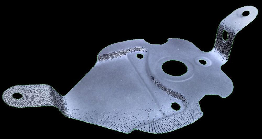
Figure 1
A part like this must be rotated in front of the optical
scanner, or the scanner must be moved to capture all
of the part.
After having worked with a coordinate measuring machine (CMM), have you ever wondered what it would be like if you didn’t actually have to work with an arm, positioning it precisely into place? You might not have to wonder any longer.
Coordinate measuring technology that is based purely on optical viewing is now possible. The sensor technology is powerful enough to scan the entire part without the need to move a scanning head. No precision moving parts means no calibration, single-click scanning, and simplified operation when compared to traditional CMM technology.
To get a better understanding of what this technology might do for fabricators, it’s important to review the evolution of coordinate measuring.
Before the advent of digital cameras or when the cameras had an unusably low resolution, manufacturers relied on contact measurement. Some shops still use this technology to capture measurements. These contact systems typically use complex moving mechanisms to guide or locate a touch probe. While these systems can be extremely accurate, they do have some limitations:
Digital cameras with usable resolution made noncontact scanning a possibility. The resolution of these sensors still is not sufficient to cover the entire volume of many parts, so an operator has to move the scanning head over the part. As a result, the scanning head and the mechanical system driving the unit heavily influence the accuracy of these hybrid systems.
Such hybrid systems definitely obtain measurements more quickly than traditional mechanical CMMs, but they still require a skilled and engaged operator to get the most out of the operation.
The resolutions of scanner/camera technology today are high enough that it is possible to scan significant volume to an acceptable accuracy and resolution without relying on complex mechanical means to move the scanning head or part. (If all of the features a shop needs to measure cannot be seen from a single viewpoint, movement of the scanning head may be necessary.)
But what resolution do we need to achieve this? One way to assess it is to assume that it is redundant to create a scanner that is much more accurate than the expansion of a part in a temperature-controlled room. For example, a 1.5-m-long mild steel part with a thermal expansion of 13 microns per meter per degree Centigrade, which has been placed in a standard temperature-controlled room (±1 degree C, or a range of 2 C), will change in size by 2 C x 13 µm x 1.5 m = 39 µm.
It would seem pointless to create a scanner that is ±3 µm when the part is changing in size by 39 µm from one minute to the next due to thermal expansion, despite being stored in a temperature-controlled room.
At this point, it is prudent to include a safety factor of 2 in these calculations.
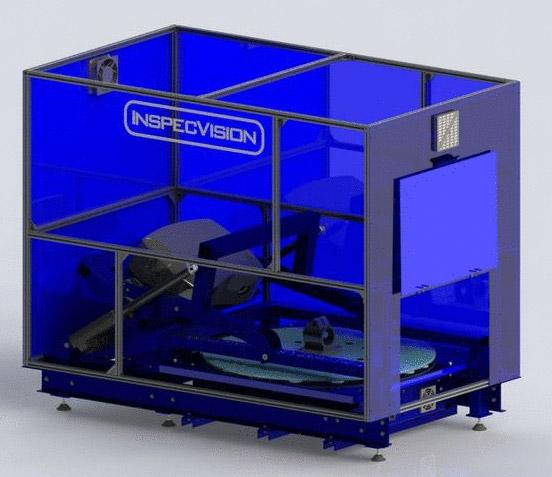
Figure 2
This optical measuring system has a scanning volume
of only 350 mm, but it has an accuracy of 10 microns.
Another important variable is subpixel resolution. Most digital cameras are either gray-scale or color. So rather than containing binary black and white pixels, they contain gray-level information ranging from black to white. Color cameras use Bayer grids and color interpolation to achieve color pixels. Either way, the level of luminosity in the pixel can be used to determine the position of a feature to subpixel resolution. A typical value for subpixel accuracy is 0.1 pixels.
With this information, a shop can calculate the required width of the scanner image in pixels.
The required accuracy is 39 µm
(Thermal expansion in temperature-controlled room)/2 (Safety factor) = 19.5 µm
1.5 million µm (Part length) x 0.1 (Subpixel resolution)/19.5 µm
(Required accuracy) = 7,692 pixels wide
Many cameras have an aspect ratio of 1.5, which means that the image height is 7,692 / 1.5 = 5,128 pixels high
Multiplying the pixel height by width (7,692 x 5,128) results in 39 megapixels.
Cameras on the market today achieve this and even higher resolution. This makes purely optical coordinate measuring a possibility.
What might some of these purely optical measurement systems look like? Here are a couple of examples.
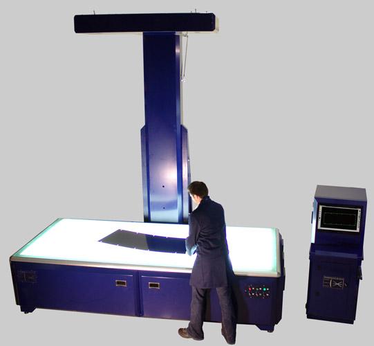
Figure 3
This 2-D optical scanner has a 35-micron inspection accuracy.
An Optical CMM. White light scanners project sequences of light onto the part. The part deforms the structure of the pattern, and the camera captures the image (see Figure 1). The advantage of a white light scanner is that it can acquire a measurement at every pixel in the camera.
Because the scanner cannot see all of the part from a single viewing position, the part must either be rotated or moved in front of the scanner, or vice versa. For most parts, a simple solution to this problem is to use a rotational table and tilting axis. Such a setup provides a complete viewing hemisphere. The accuracy and resolution of such a system are limited only by the resolution of the optical devices.
An optical CMM (see Figure 2) works with a single click after the part is put on a table; after the click, the scan and inspection commences. Because the system measures every visible surface every time it scans the part, it is likely to detect miniscule and extra features. In addition, because the optical CMM produces a measurement at every pixel in the camera, it can process the highly ordered data much more easily than the disordered point clouds from laser scanners mounted on traditional CMM devices.
Many systems like this can detect automatically when they need to be calibrated. For example, if the camera suffers trauma and needs to be calibrated, the system detects this and provides an indication that this mechanical deficiency needs to be addressed.
2-D Inspection. This technology is not limited to use on just 3-D parts. The inspection of 2-D parts is best achieved with a 2-D scanner using this optical capability, rather than a 3-D optical scanner.
In one example of a machine with a 3-m-wide measuring bed (see Figure 3), the device’s two 37-MP cameras can acquire up to 80 million measurements in less than 0.1 second.
Again, the advantages of this optical measuring machine are similar to those of 3-D equipment. It is fast and automated, requires no programming, requires no jigging, provides robust inspection, and automatically signals when calibration is necessary.
Large-volume Scanning. One of the really interesting advances in optical systems is the field of photogrammetry, particularly texture-based photogrammetry.
Until recently photogrammetry systems involved attaching optical markers to an object to create unique optical features. The operator would simply take pictures of these markers from different positions, and the software would identify these unique features, matching them in each of the images. This correspondence information then could be used to calculate the marker positions, the camera, and sometimes the camera’s calibration parameters.
New advances in optical feature detection eliminate the need to attach markers to an object, as long as the object possesses a textured surface, such as bricks or rust. These surface textures can be used as features and located in multiple images to allow calculation of surface measurement points.
Systems like this are extremely flexible, to the point where the same system can be used to measure objects the size of a thimble or a planet (see Figure 4).
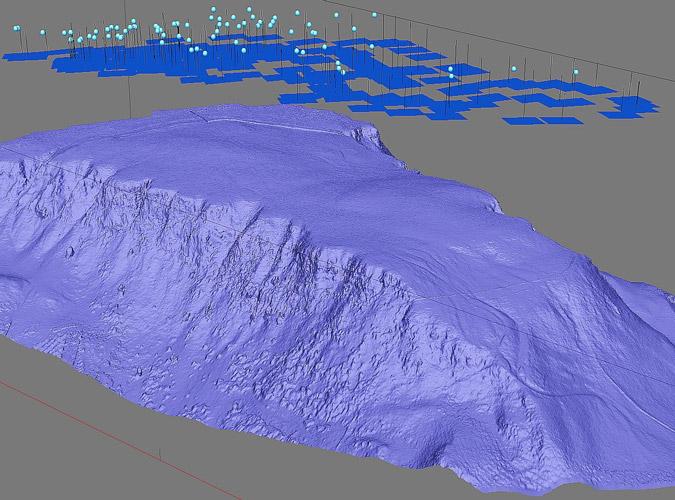
Figure 4
Advances in photogrammetry mean that an optical scanning of a mountainous surface can translate into a 3-D map of the mountain. Affixing strategically placed markers on the mountain surface and taking pictures of those markers to help create a database that can be used to create a 3-D map is no longer necessary.

The Fabricator is North America's leading magazine for the metal forming and fabricating industry. The magazine delivers the news, technical articles, and case histories that enable fabricators to do their jobs more efficiently. The Fabricator has served the industry since 1970.
start your free subscription
Easily access valuable industry resources now with full access to the digital edition of The Fabricator.

Easily access valuable industry resources now with full access to the digital edition of The Welder.

Easily access valuable industry resources now with full access to the digital edition of The Tube and Pipe Journal.

Easily access valuable industry resources now with full access to the digital edition of The Fabricator en Español.
In this episode of The Fabricator Podcast, Caleb Chamberlain, co-founder and CEO of OSH Cut, discusses his company’s...


