


Contributing Writer
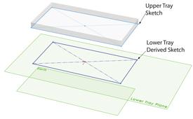
Figure 1The Lower Tray is linked parametrically by a Derived Sketch to the controlling sketch in the Upper Tray.
As promised last month in Part II, we're going to explore a few techniques for modeling sheet metal parts within the context of a master assembly. What we want to end up with is a design that allows us to explore various size changes of the overall product while having the component parts stretch or shrink automatically.
(The usual disclaimer: If you're not using the same 3-D CAD software as I am, then you'll have to translate some of the terminology. However, the concept of parametric modeling is widely applicable.)
We have already completed the Upper Tray model. Our Lower Tray will be similar to but not identical to the Upper Tray. We want the platform size of the Lower Tray to always be the same as the Upper Tray. Why not use the same sketch that was used for the Upper Tray to make the Lower Tray?
One way to do that is to use a Derived Sketch—sort of like a copy but more like a friendly doppelganger. With one exception, the derived sketch is identical to the original sketch. That exception is the plane on which it exists. If the controlling sketch is edited, all sketches derived from it will automatically change.
To create the derived sketch shown in Figure 1, I clicked on the original sketch to select it, and then while holding the CTRL key, I clicked on the Lower Tray Plane, selecting both the sketch and the plane (or surface). Then I used the menu command Insert>Derived Sketch. The final step constrained the derived sketch to the origin of the Upper Tray so it is properly aligned in the assembly.
Are there other ways to create a parametrically linked sketch? As Sarah Palin might say, "You betyer mousie!"
You could start a new sketch on the Lower Tray Plane and then use the Convert command while selecting the line entities in the sketch for the Upper Tray to create linked sketch entities for the Lower Tray. However, that takes several mouse clicks. You also could draw a new sketch and dimension it just like the Upper Tray and set up equations so the dimensions between the sketches are linked to be identical. That takes some mastery of the equation tool interface.
I'm sure other techniques would work as well. The best modeling technique is the one that satisfies your design goal efficiently.
You may recall that we modeled the Upper Tray using sheet metal features from the outset. Just to explore a variety of modeling techniques, let's create the Lower Tray as a six-sided solid and convert it into a sheet metal model. I'll leave it to you to count how many surfaces that will be. The following steps are specific to 2009 and later versions of the software I'm using.
First, use our newly derived sketch to extrude it into a volume that represents the total overall size that we want for the Lower Tray. Figure 2 shows the resulting solid brick. It may not be clear from the illustration, but the direction of the extrude is towards the Earth since I defined the Lower Tray Plane location at the top surface of the tray.
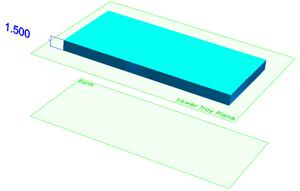
Figure 2The Lower Tray model starts out as a simple solid brick.
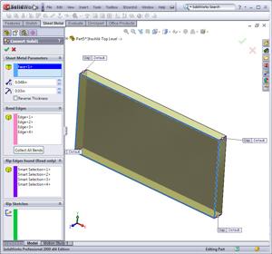
Next, use the Convert to Sheet Metal tool (see Figure 3). The procedure requires selecting a stationary face and the edges that represent bends. Then you simply fill out the form to set values for the material thickness, bend radius, corner gap distance, and bend relief type. After you click to confirm the settings, the software converts the solid brick into a sheet metal tray that can be unfolded (see Figure 4). Note that I've rotated the part in Figure 4 to make it easier to see the sheet metal characteristics of the part.
If you need to set the bend deduction parameters so the part will unfold accurately, you can edit the Sheet Metal feature in the Feature Manager. The Convert to Sheet Metal tool is so simple that it feels like cheating. However, I still find excuses to model sheet metal parts using the "long-hand" methods of old.
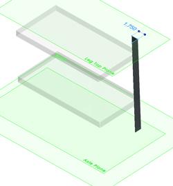
Figure 5 gives you an overview of my procedure for modeling a leg part. I selected the Leg Top Plane and then sketched two lines in the approximate form of an L. I made the two line segments equal to each other and dimensioned one of them to be 1.75 inches long.
To link them parametrically to the size of the Upper Tray, I assigned collinear sketch relations between the corresponding edges of the Upper Tray and the line segments. That completed the sketching stage for the leg model.
To create the 3-D model, I used the Base Flange tool. That tool needs to know how long the leg is and what kind of sheet metal it is to be made from. To set the length, I used the Offset From Surface option and selected the Axle Plane. Making a quick engineering decision, I decided that 0.625 in. of material would be enough to hold the axles. To set the sheet metal parameters, I used the Gauge Table option, which allows me to select the material gauge, and then let the table fill in the values for bend radius and k-factor automatically.
Again, a designer probably could find a half dozen different ways to model this leg, all of them with their own merits. Sketching two lines and letting the software do the rest seemed good to me.
In Part IV of this series, we'll continue modeling components of our grill project like the wheels, axles, retaining caps, and so forth.
Keep in mind that this top-down modeling technique we're using is not the only way to do this work. It may not even be the best way in every situation. However, when it comes to virtual prototyping, it is efficient to use parametrically driven features. It takes some time to set up initially, but it will pay off later by speeding the revision process. The use of reference geometry to control parametric features reduces the complexity of figuring out what drives what.
Gerald would love to have you send him your comments and questions. You are not alone, and the problems you face often are shared by others. Share the grief, and perhaps we will all share in the joy of finding answers. Please send your questions and comments to dand@thefabricator.com.


The Fabricator is North America's leading magazine for the metal forming and fabricating industry. The magazine delivers the news, technical articles, and case histories that enable fabricators to do their jobs more efficiently. The Fabricator has served the industry since 1970.
start your free subscription
Easily access valuable industry resources now with full access to the digital edition of The Fabricator.

Easily access valuable industry resources now with full access to the digital edition of The Welder.

Easily access valuable industry resources now with full access to the digital edition of The Tube and Pipe Journal.

Easily access valuable industry resources now with full access to the digital edition of The Fabricator en Español.
In this episode of The Fabricator Podcast, Caleb Chamberlain, co-founder and CEO of OSH Cut, discusses his company’s...


