


Contributing Writer
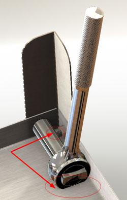
Figure 1: The location of the bolts prevents a socket wrench from being used for assembly.
Tony H. read Part VII of this series (Precision Matters, The FABRICATOR, July 2010, p. 33) and noted that we had left room for a socket, but not necessarily for the ratchet (see Figure 1). Furthermore, he noticed that after we install the first bolt in a corner, the adjacent bolt will restrict the tooling access.
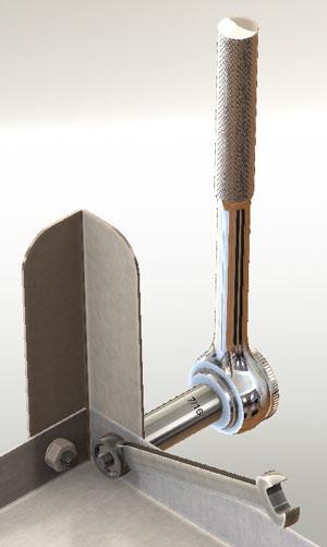
Those are both excellent observations. Remember that design review is important! We’ll have to remember to note that a box end wrench will be needed (see Figure 2).
Of course, we could have staggered the fasteners in the corner and used larger flanges on the shelves to address Tony’s concern. That might even make the assembly stronger, but I’ll leave that design improvement up to you.
Part VIII of this series of articles ended with the intent to work on the parts for the charcoal pan (see Figure 3). We are going to continue our theme of locating features in the context of our top-level assembly.
(The usual disclaimer: If you’re not using the same 3-D CAD software as I am, then you’ll have to translate some of the terminology. However, the concept of parametric modeling is widely applicable.)
In Figure 3 we have two short end skirts. These are identical to each other. There also are two longer side skirts—also identical—that have vent holes and bent flanges to support the future fire pan.
This plan—or design constraint—offers the benefit of using as many identical parts as possible, which reduces setup cost in manufacturing and possibly reduces confusion during assembly. So far this design constraint pre-sents no problems, but we’ll abandon it quickly if it is to our advantage to have dissimilar parts. For example, one end might have holes for a push handle.
Let’s start with the small end skirt. We’ll make it out of 18-gauge (0.048-inch) stainless steel. Because it tucks inside the top shelf, we’ll need a jog offset bend to keep the surface flush against the leg when installing the bolts (see Figure 3). A second jog bend near the top serves primarily to stiffen the part and also adds a bit of aesthetic style.
Figure 4 shows the sketch and related dimensions that I used to start modeling the end skirt. I left 0.10 in. between the inside edges of the legs and the vertical edges of the end skirt to allow for the bend radius of the legs. The bottom edge of the end skirt overlaps the shelf by 0.880 in. The top edge projects above the top of the leg by 1.50 in.
All of these dimensions are fairly arbitrary. The main idea is that the part is modeled in the context of the main assembly. If the relationship between the legs and the top shelf changes, then the side panel should stretch to automatically fit.
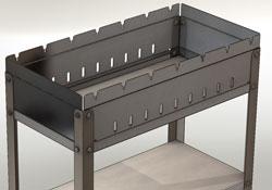
Figure 3: A preview of the parts that we want to model this session is shown.
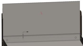
To create the offset jog bends, the CAD software I’m using needs a single line sketch that indicates where the jog is to be (see Figure 5a). I’ve dimensioned the jog bend line 0.125 in. above the top edge of the shelf. That should be enough to allow for the bend radius of the tooling. Feel free to adjust this to match your shop’s tooling. If the size of the flanges on the shelf should change—for better hand tool access, perhaps—the jog bends automatically will move as needed.
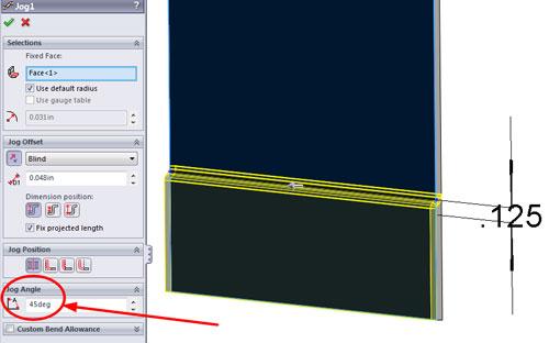
In Figure 5b you see the PropertyManager dialogue for the Jog feature. Because I want the offset to match the material thickness (0.048 in.) of the shelf, I need to reduce the bend angle of the jog from the default 90 degrees to something less—45 degrees, for example. This allows for the tooling radius of the jog. You certainly will want to change all of these parameters to match the tooling in your manufacturing facility.
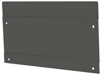
To add the second jog, I created another sketch. This time it was dimensioned 1.50 in. from the top edge of the skirt. Because it is just an aesthetic detail, it does not need to be dimensioned relative to other parts in the assembly. To finish up the skirt, I cut holes for the bolts and added fillets to the top corners to improve the safety of the final assembly. The completed end skirt is shown in Figure 6.
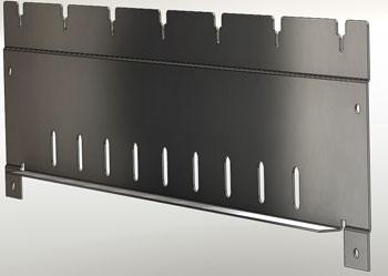
In Part X of this series we’ll work on the skewer skirt shown in Figure 7. As a heads-up, the modeling process is nearly identical to that used for the end skirt with the addition of a flange and a pattern of cutouts for the vents and skewer slots.
Keep in mind that this top-down modeling technique we’re using is not the only way to do this work. It may not even be the best way in every situation. However, when it comes to virtual prototyping, it is efficient to use parametrically driven features. It takes some time to set up initially, but it will pay off later by speeding the revision process. The use of reference geometry to control parametric features reduces the complexity of figuring out what drives what.
Gerald would love to have you send him your comments and questions. You are not alone, and the problems you face often are shared by others. Share the grief, and perhaps we will all share in the joy of finding answers. Please send your questions and comments to dand@thefabricator.com.


The Fabricator is North America's leading magazine for the metal forming and fabricating industry. The magazine delivers the news, technical articles, and case histories that enable fabricators to do their jobs more efficiently. The Fabricator has served the industry since 1970.
start your free subscription
Easily access valuable industry resources now with full access to the digital edition of The Fabricator.

Easily access valuable industry resources now with full access to the digital edition of The Welder.

Easily access valuable industry resources now with full access to the digital edition of The Tube and Pipe Journal.

Easily access valuable industry resources now with full access to the digital edition of The Fabricator en Español.
In this episode of The Fabricator Podcast, Caleb Chamberlain, co-founder and CEO of OSH Cut, discusses his company’s...


