


Contributing Writer
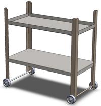
: Figure 1: The model needs holes for bolts as well as nuts and bolts to hold it together.
Our design project has progressed to the basic structure shown in Figure 1. Magically, the trays and legs are staying in place without any visible means of support. Now is the time for all good nuts and bolts to be added to the model.
(The usual disclaimer: If you’re not using the same 3-D CAD software as I am, then you’ll have to translate some of the terminology. However, the concept of parametric modeling is widely applicable.)
We’re discussing boring holes as a process, not as a topic lacking in interest. Undoubtedly, several techniques could be used to model the holes for the bolts. We’re going to limit ourselves to parametric techniques. In particular, if the elevation of the shelves should change, we want their mounting holes and fasteners to automatically update to the new location.
I’m proposing adding holes to a shelf, then making holes in the leg that are parametrically located by the holes in that shelf, and finally locating the bolts by mating them to the holes. Thus, as the shelf moves, the holes move and the bolts move with the holes.
A different but equally valid technique would be to locate the bolts relative to our reference geometry—mate them at some distance from the planes—and then model the holes to be concentric with the bolts. In this way, as the planes move, the bolts move and the holes move with the bolts.
My reason for selecting one technique over the other is largely driven by wanting to make sure we don’t unintentionally locate the holes too close to a bend. It’s all about design for ease of assembly. This is entirely a matter of preference. If you opted to use holes in the legs to drive the position of the shelves and mounting hardware, I would not object.
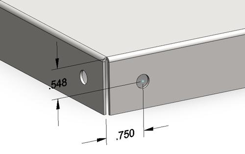
Figure 2a is a closeup of the sketch used to create one of the holes in the corner of the lower tray. In this example, I’m using a tool called the Hole Wizard. I like this tool for several reasons:
As usual, there are myriad techniques for modeling holes—extruded cuts, revolved cuts, and perhaps even sweeps or cavities. Each technique has its advantages, and I encourage you to explore using all of them.
In the example in Figure 2a, I’ve chosen to dimension the center of the hole at a distance from the outside of the bend. It takes a little bit of mental gymnastics to consider that the edge of the hole needs to be at least three material thicknesses from the inside of the bend in order to avoid distortion and tearing during forming. Because the material is 18 gauge and the hole is 0.257 inch diameter, and the bend radius is 0.048 in., the hole center needs to be at least 0.321 in. from the outside of the bend. Please feel free to check my math, if you like.
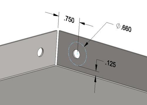
In the example in Figure 2b, the same hole is being located relative to the inside surface of the tray. A bit of construction geometry—the 0.660-in.-diameter circle—represents the approximate size of a standard 7?16-in. socket wrench, which is the tool that could be used to tighten a ¼-20 nut. I’ve chosen to leave a 1?8-in. gap between the sheet metal and the outside of the imagined tool (see Figure 3).
I’ve posted 3-D models of some common hand tools both on the SolidWorks® discussion forum (https:// forum.solidworks.com/index.jspa)—search for “handy hand tools?—and on 3-D Content Central® (http://www. 3dcontentcentral.com)—search for “gerald davis.?
I’m sure you can engineer several “better? ways to dimension the hole locations for our bolts. The best technique will depend entirely on your design intent.
If you noticed that Figure 2b might be dimensioning to the end of the bend radius and that changing the bend radius would change the location of the holes and that result could be undesirable, you get extra credit and a gold star on your paper!
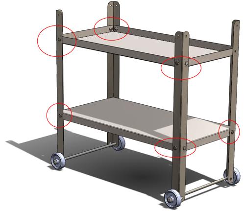
In Part VIII of this series, we’ll add holes to the legs and mate the bolts to the holes as shown in Figure 4. Perhaps we’ll even get started on the charcoal pan and vents.
Keep in mind that this top-down modeling technique we’re using is not the only way to do this work. It may not even be the best way in every situation. However, when it comes to virtual prototyping, it is efficient to use parametrically driven features. It takes some time to set up initially, but it will pay off later by speeding the revision process. The use of reference geometry to control parametric features reduces the complexity of figuring out what drives what.
Gerald would love to have you send him your comments and questions. You are not alone, and the problems you face often are shared by others. Share the grief, and perhaps we will all share in the joy of finding answers. Please send your questions and comments to dand@thefabricator.com.


The Fabricator is North America's leading magazine for the metal forming and fabricating industry. The magazine delivers the news, technical articles, and case histories that enable fabricators to do their jobs more efficiently. The Fabricator has served the industry since 1970.
start your free subscription
Easily access valuable industry resources now with full access to the digital edition of The Fabricator.

Easily access valuable industry resources now with full access to the digital edition of The Welder.

Easily access valuable industry resources now with full access to the digital edition of The Tube and Pipe Journal.

Easily access valuable industry resources now with full access to the digital edition of The Fabricator en Español.
In this episode of The Fabricator Podcast, Caleb Chamberlain, co-founder and CEO of OSH Cut, discusses his company’s...


