


Resistance welding electrodes: More for less
Best practices prolong electrode life
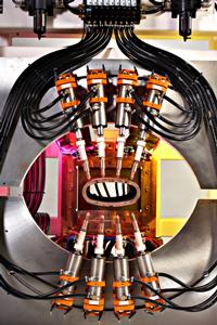
This multigun resistance welding system is designed for automotive exhaust systems.
Resistance welding often is viewed as a process shrouded in mystery, and one of its most misunderstood components is the welding electrode. Electrodes have a profound effect on weld integrity and, ultimately, process costs.
Improper electrode use is expensive in many ways, the most obvious of which is short electrode life. Costs associated with poor weld quality often can be traced back to faulty electrode usage. With today's high cost of copper—to say nothing of the extra labor and lost production time—wearing out electrodes prematurely has become more expensive than ever.
Resistance Welding Electrode Selection
When tooling up a new resistance welding application, the first step is to match the electrode size and shape to the thickness and alloy of material being welded. Galvanized metal with zinc coatings require special attention (see Considerations for Coated Metal sidebar). Electrode selection guidelines are available from electrode manufacturers and the Resistance Welding Manufacturing Alliance (RWMA).
Material thickness and desired weld nugget size affect selection of the electrode face, or tip end. As a cost-saving measure, many operators replace one-piece electrodes with a shank and cap assembly. The electrode shank can be reused many times, and the cap-type tip, available in many configurations, can be replaced.
A straight electrode with a pointed nose and a -inch-diameter weld face suits most sheet metal welding applications, while a dome-shaped nose can be used for applications in which alignment is difficult to maintain.
Offset-type, double-bend electrodes are handy for difficult-to-reach welds, but they are weak and prone to deflection. Although electrodes with an offset nose, whether straight or double-bend types, can help in limited-access situations, they should be avoided unless absolutely required because the offset nose design wears rapidly and is difficult to dress. Instead, try to use offset electrode holders and straight tips whenever possible. Truncated and radius-nose electrodes are recommended for spot welding aluminum, while flat-faced and swivel tips often are used as backup electrodes and to achieve a smooth show surface.
To produce an attractive show surface, shops sometimes try to weld thin material using an electrode with a large-diameter weld face on each side. The electrode's large surface area, in relation to the thin material being welded, allows too much heat into the part, producing a burned, poor-quality weld. To produce an attractive show surface on one side of a part, use a wide-face electrode on the show side and a much smaller-diameter weld face on the back side, thus concentrating the heat in a small area.
Tapered Versus Threaded Shanks
Different electrode configurations suit different welding applications. An electrode with a tapered shank that fits into a holder is most common and costs less than a threaded electrode. However, if the application requires the weld face to be at a consistent datum, such as in tooling designed for welding multiple projections, tapered electrodes do not allow the consistent registration point obtainable by threading an electrode to a positive shoulder.
Ensure an electrode's thread or taper is strong enough to withstand the weld force. A taper that is too small will make it difficult to remove the electrode and shorten electrode and shank or holder life. In applications that require high weld force, threaded or flanged electrodes can be easier to change, with less wear on tooling components. When installing electrodes, especially the tapered shank type, try using a very thin coating of castor oil or other electrically conductive grease; this can make the electrode much easier to remove after use.
Well-dressed Resistance Welding Electrodes
Proper dressing of the electrode's weld face is critical for high weld quality and long electrode life. The electrode's weld face should be maintained at its original shape and size during its life. There are many ways to maintain well-dressed electrodes, starting with simple hand files and advancing to hand-held, air-operated rotary dressing tools and high-speed, automated dressing systems. Production environments, such as robotic spot welding cells, may call for such automatic electrode dressers.
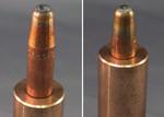
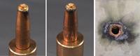
Figure 1These electrodes were operated with too much heat. Note the discoloration of the tip and the way the weld face has softened, losing its shape and flattening.
Many find that removing electrodes from the welding machine on a set schedule and dressing them in quantity—often using a separate drill press with special cutters—is superior to attempting to dress them on the welding system. Each production situation will determine which electrode dressing system is best.
In Control
Modern programmable resistance welding controls have numerous standard features to help improve quality and extend electrode life. For instance, a weld control that can program heat (weld current) step-ups to compensate for normal electrode wear can greatly extend the time between dressings. Conduct a formal tip life study to determine the total number of welds an electrode should make before the heat stepper is actuated and how many steps (weld heat increases) can be made before the tip produces marginal welds. The study also should determine when an electrode should be dressed and changed.
Many operators tend to make resistance welds using much more current and weld time than are actually needed to produce a strong joint. Excessive current causes expulsion and overheats the part and the electrodes. As a rule, resistance spot welds should be made at a high heat setting and short weld time. Weld times often are set too long in an effort to compensate for a resistance welding machine with a kilovolt-amp rating that is marginal for the application. Excessive weld time shortens electrode life and leaves a large, ugly heat-affected zone in the part.
A control with weld current monitoring should be programmed to ensure that proper amperage is always delivered to the part. Welding within the range determined as ideal for the part's material type, thickness, and required weld strength prevents the process from getting out of control.
Be Cool
The importance of adequate water flow at the proper temperature cannot be overemphasized. Excess heat degrades electrode life, and adequate water cooling for electrodes and other tooling components helps ensure quality welds. Some try to cool welding systems using a recirculating pump and a 55-gallon drum of water, but this is rarely adequate. Others cool welding systems with rooftop water towers that are open to the air and collect dirt and dust and promote algae growth. These contaminants can plug a welding machine's water-cooling passages and cause damage. Still others just run city water straight from a faucet. While this is better than no cooling water at all, it is expensive; electrodes need about 1.5 gallons of water per minute—and that can add up to a big water bill.
By far the most cost-effective way to keep welding equipment operating at peak efficiency is a self-contained, closed-loop, water-recirculating chiller engineered for resistance welding. When using a chiller, however, be sure to avoid setting the water temperature below the prevailing dew point. Otherwise, the resulting condensation in the weld control and weld transformer will eventually damage components. A good amount of water—cool but not too cold—ensures maximum welding machine and electrode life, plus consistent quality welds.
The electrodes in Figure 1were operated with too much heat. An improper weld schedule or inadequate water cooling could have caused this problem. Note the discoloration of the tip and the way the weld face has softened, losing its shape and flattening. Electrode holders and some electrodes, mainly double-bend offset types, have a small-diameter brass tube installed with the end cut on a 45-degree angle, quill-style. This tube forces cooling water to flow all the way to the end of the electrode's internal water-cooling cavity. Since these tubes bend easily, operators who do not understand their importance often throw them away, thus guaranteeing a shortened electrode life.
The Recipe for a Smooth Resistance Weld
When setting up a new application, base the welding schedule "recipe" on a well-known starting point for the material being welded, using weld schedules such as those available from RWMA reference materials, including books and seminars. These materials also explain the proper interrelationships among process variables, which include forging pressure (force), welding current (amps), and weld time (duration of current flow). In addition, most modern programmable welding controls allow the selection of features such as upslope time, squeeze time, percent current (phase shift heat control), pulsation, and downslope time.
Of course, the weld schedule alone isn't guaranteed to save consumable life. Operators must properly use and maintain the resistance welding system to attain a truly efficient and reliable weld, time after time.
Weld Time: Less Is Best. The less time the electrode spends conducting current, the longer the electrode life will be. Ideally, a spot welding operation should produce little to no expulsion or sparking. Many believe that if the process isn't "throwing fire," then the welds are no good. Nothing could be further from the truth. The "fire" being thrown is expelled base material from the part, along with a portion of the electrode face—again, shortening electrode life.
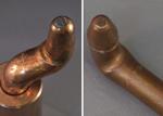
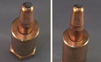
Figure 2Figure 2 Click to view image largerThese electrodes deflected or skidded during use, caused by excessive weld force or misaligned upper and lower electrodes that are not parallel to the axis of motion or perpendicular to the part. Note the half-moon imprint on the weld face.
Maintenance. A well-maintained welding machine, with no sloppiness in the force delivery system, ensures maximum electrode life and enhances weld quality. Rebuilding or replacing worn pneumatic weld cylinders and adjusting or replacing worn slide gibs and rams ensure consistent weld force. A preventive maintenance schedule should include cleaning and tightening the machine's primary and secondary connections. Solid electrical connections result in less heat and current loss in the machine's secondary loop.
Deflection. The half-moon imprint on the weld face in Figure 2indicates the electrode deflected or skidded during use. This may have been caused by excessive weld force or misalignment of the upper and lower electrodes that are not parallel to the axis of motion or perpendicular to the part. Such deflection lessens weld quality and shortens electrode life.
While sometimes not readily apparent, proper fixture design promotes longer electrode life, especially in projection and cross-wire welding. Design as much rigidity as possible into the fixtures, and use the shortest possible electrodes, shanks, and holders. Longer- than-needed component and stackup distances promote deflection. An open design promotes cleanliness and better air cooling, so allow as much clearance as possible around the tooling details.
Mechanical Deformation. In an effort to improve productivity, operators sometimes set a machine's airflow controls wide open. While this allows the force delivery system to travel in the shortest amount of time, it also slams the soft copper electrodes into the workpiece and can quickly deform electrodes (see Figure 3). Deformation shortens electrode life and increases the contact area that passes current, causing inconsistent weld quality.
Newer machines eliminate airflow control altogether with all-electric, servo-control designs that can decelerate the weld tip just before it contacts the part.
Fit-up. Proper part fit-up is critical to a successful resistance welding process, especially in a production situation. The welder is not a forming machine. Any of the machine's clamping force used to overcome springback and form the part represents forging force taken away from the weld.
Force. Proper weld force is vital to ensure not only weld quality and electrode life, but also operator safety. Insufficient force can cause weld blowouts, which damage electrodes, piece parts, and tooling. The operator, attempting to increase production, often sets the squeeze time (tip travel time) portion of the weld schedule too short, causing the weld control to fire before reaching full weld pressure (seeFigure 4). This damages the electrode to the extreme, blows holes completely through the sheet metal, ruins parts, and potentially causes serious injury.
Doing It Right
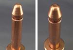
Under optimal operation, resistance welding electrodes exhibit even wear and no heat discoloration (seeFigure 5). With proper pressure, current, and welding time, the electrode will maintain a uniform weld face and, most important, will have a maximum useful life.
Although resistance welding can be complex, with a suitable application it yields consistent, cost-effective, high-quality results. But no matter how optimal the application is using the latest and greatest welding technology, the process is only as good as the electrodes delivering the welding current and force to the part.
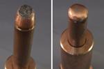
Figure 3Electrodes can deform if an operator sets the machine's airflow controls wide open, causing the soft copper electrodes to slam into the workpiece.
For welding coated materials, some new electrode geometries and alloys have proven superior. For example, dispersion-strengthened electrodes often are used today, as are tips made from an alloy of zirconium, chromium, and copper.
The galvanized coating (zinc) tends to be picked up on the weld face (see figure). After just a few welds, the zinc coating wants to alloy and embed itself in the copper. Avoid welding after the tip becomes heavily coated and mushroomed. If not properly dressed or replaced, electrodes with excessive zinc buildup can produce inferior, "cold" welds.
When working with galvanized metal, some operators condition new electrodes by making a few preliminary welds on scrap material before starting production. The first few welds new electrodes make can be unpredictable, so such conditioning allows the zinc coating to stabilize during the initial portion of the electrode's life. As long as the weld heat is set to properly compensate, the practice should have little effect on weld quality.
James L. Dillard is vice president of manufacturing and engineering at T.J. Snow Company Inc., 6207 Jim Snow Way, Chattanooga, TN 37421, 423-894-6234, www.tjsnow.com. For more information about the Resistance Welding Manufacturing Alliance, visit www.aws.org/rwma.
Electrode photos by Samuel C. Snow. Machine photo by David B. Jenkins, Chickamauga, Ga.
About the Author
About the Publication
subscribe now

The Fabricator is North America's leading magazine for the metal forming and fabricating industry. The magazine delivers the news, technical articles, and case histories that enable fabricators to do their jobs more efficiently. The Fabricator has served the industry since 1970.
start your free subscription- Stay connected from anywhere

Easily access valuable industry resources now with full access to the digital edition of The Fabricator.

Easily access valuable industry resources now with full access to the digital edition of The Welder.

Easily access valuable industry resources now with full access to the digital edition of The Tube and Pipe Journal.

Easily access valuable industry resources now with full access to the digital edition of The Fabricator en Español.
- Podcasting

In this episode of The Fabricator Podcast, Caleb Chamberlain, co-founder and CEO of OSH Cut, discusses his company’s...
- Trending Articles
1
AI, machine learning, and the future of metal fabrication

2
Employee ownership: The best way to ensure engagement

3
Steel industry reacts to Nucor’s new weekly published HRC price

4
How to set a press brake backgauge manually

5
Capturing, recording equipment inspection data for FMEA
