


Contributing Writer
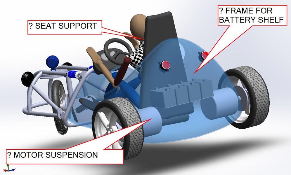
Figure 1a
This virtual prototype of an electric go-cart needs a suspension
system for the motors, a frame for the batteries,
and something to hold the driver’s seat.
Editor's Note: If you would like to download the 3-D CAD files associated with this column, click here.
In the previous edition of this column, we looked at a CAD technique for modeling the go-cart body shown in Figure 1a. This model is a work-in-process, and as a result, the motors are not connected to anything except for the wheels. The batteries are floating in space, as is the driver’s seat.
Figure 1b shows a more detailed CAD model—a frame that will eventually support the seat is shown. The tubing surrounds the batteries. There also are connection points for suspension components.
As a disclaimer, the debate about the merits of the product shown are part of the design process, but not part of our scenario. Our mission is to use the concept model from Figure 1a to create a frame as shown in Figure 1b.
In the theme of disclaimers, while one type of CAD software is used in conjunction with this column, numerous other CAD modeling packages can do this same thing. This article is intended as a demonstration of design evolution more than as a tutorial on operating CAD software.
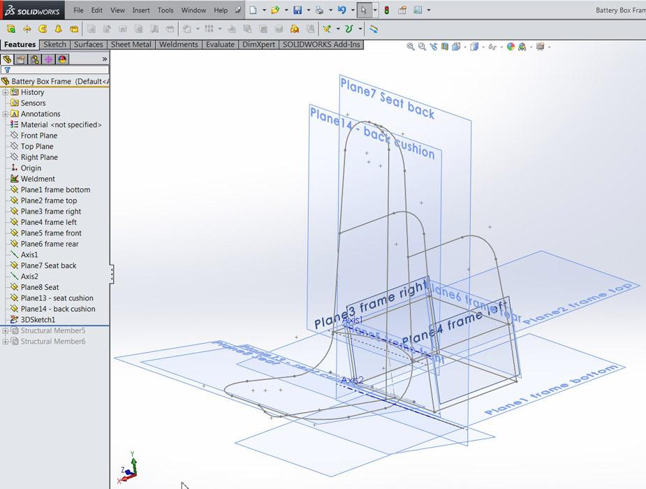
Figure 2a is a screen shot of the go-cart assembly with just a few of the components isolated in the view. Before this image was captured, a new component had been inserted into the assembly. The only hint of its existence is the fact that you can see reference geometry—planes—that have been created inside that new component. That new component is going to be our “battery box frame.”
The left and right planes were adjusted to match the size of the motors and the stack of batteries. The front and rear planes for the frame were positioned to match the preliminary seat and body shape. In addition to six planes for the battery box, additional planes were set up for the seat.
This frame creates a roll cage around the driver. The planes for the seat—as opposed to those for the seat cushion—define the cage’s depth that the driver is sitting in.
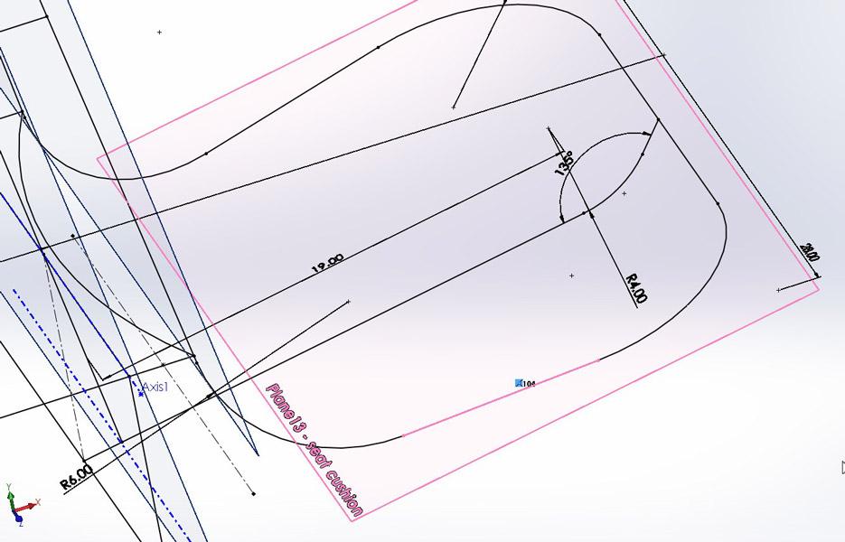
The consequence of setting up all of these reference planes is hinted at in Figure 2b, which can be confusing to look at. In this image, all of the planes are turned on. Upon close examination, we can see the gray lines of the 3-D sketch that will become the weldment frame.
Numerous CAD tips are buried in Figure 2b:
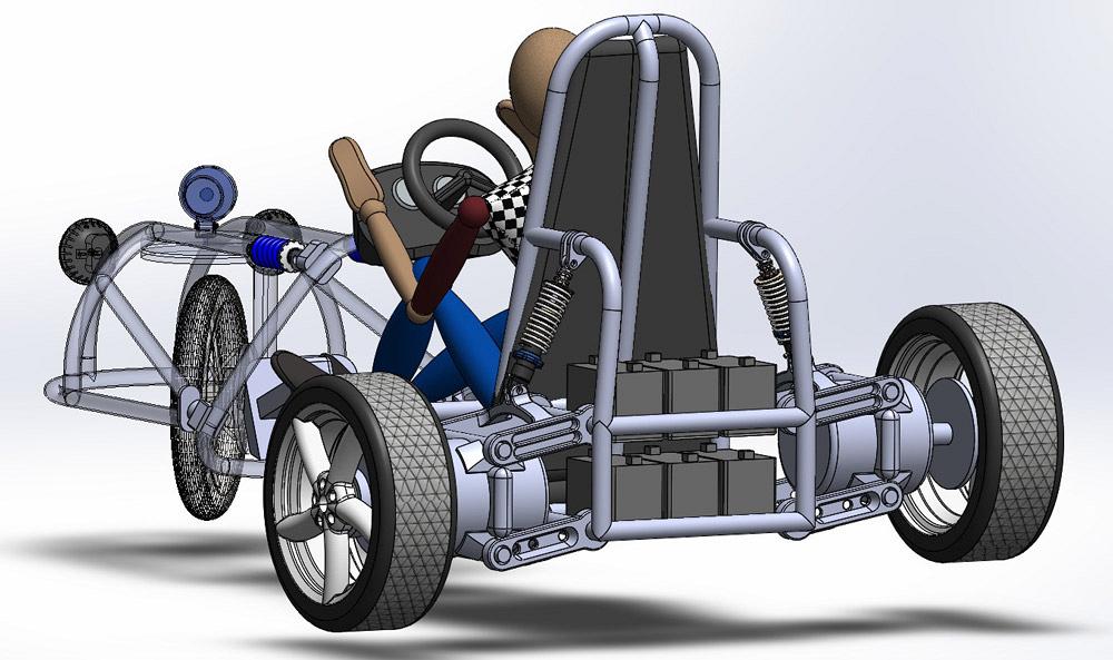
Figure 1b
Upper and lower control arms allow the motors to swing
vertically and remain parallel to earth (parallel to the car,
anyway).
In this screen shot, a line segment that is the perimeter of the seat frame has been selected, shown in pink. This pink line segment is “on plane” with Plane13—seat cushion. The pink line also is at an angle for the comfort of the driver’s thighs. In addition, there is an opposite side to model in this symmetrical seat.
“Symmetry” is one example of 2-D sketch relations that don’t exist in 3-D sketch space. This battery box frame example is symmetric about the midplane of the cart.
Symmetry is a behavior that is made by hand in a 3-D sketch. (CAD tip: Instead of a construction line, as in 2-D sketching, use a plane when setting up symmetrical behavior in 3-D sketching.)
As with many CAD operations, a designer can find many ways to get a job done. As an example of one method, our Plane13 takes care of keeping the seat cushion flat relative to itself and at an angle relative to the floor of the cart. If the seat cushion angle needs to change, then Plane13’s angle is edited. The line segments that are related to it will follow the change.
To control the width of the front of the seat, a few 3-D sketching tricks are used. The line segment that is the front edge of the seat was drawn first. It was drawn on Plane13. That line segment is perpendicular to the midplane of the cart. A sketch point at the midpoint of that line segment is coincident with the midplane of the cart. That makes this line segment behave in a symmetrical way. It was filleted to the two line segments at the sides of the seat to create the left/right/front seat edge shown in Figure 2c.
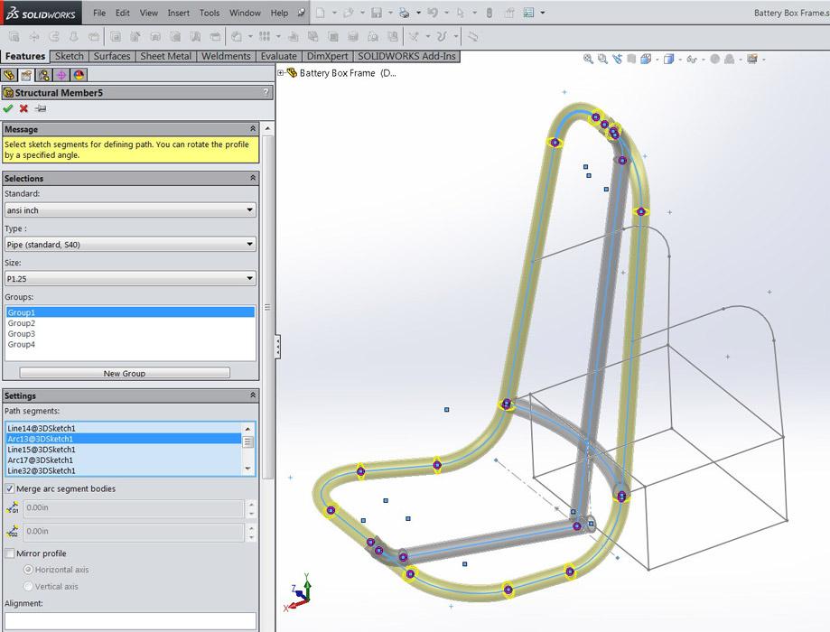
The 3-D line segments are among those used to set up the tubing path (see Figure 3a). This Structural Member in our Weldment was defined with several Groups of line segments. Using multiple groups allows the software to handle the corner treatment.
(These wonderful weldments are no exaggeration. As with sheet metal functionality in SolidWorks, I find that the weldment tools speed the modeling process and are nearly entertaining to use!)
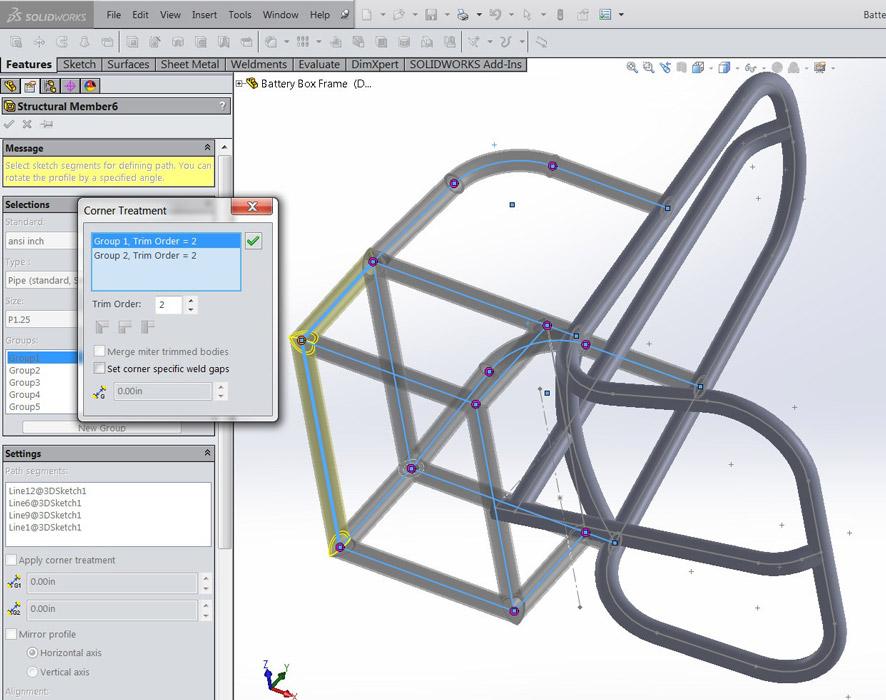
Where three tubes intersect, several corner treatment options are available. Figure 3b shows how a nice result was obtained by clicking on the (purple) dot at the intersection and selecting options in the pop-up dialog. The convenience of corner treatments is one of the best reasons to use Weldment functionality—as opposed to manually modeling with swept profiles. Well, the Cut List functionality is compelling too.
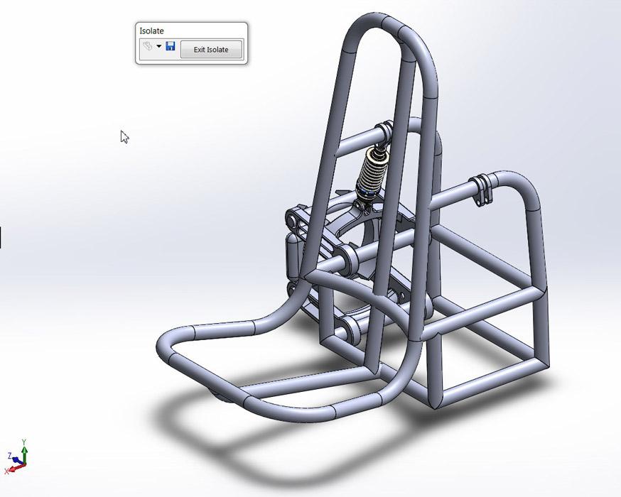
Shop technology and 3-D CAD: In-context modeling Techniques used to model weldments include 3-D sketching with external geometry Columnist Gerald Davis continues his work on a go-cart body. This time the focus is on modeling weldments with an eye on accommodating future edits.The resulting weldment—also known as the battery box frame—is emerging in Figure 4a. Only one side of the motor mount has been assembled so far. This suspension system is a four-bar link design. The upper and lower arms are two of the bars. The vertical clamp that holds the motor is a third bar. The weldment we just made completes the four-bar link. This system allows for independent motion of the motors while keeping the wheels perpendicular to the ground.
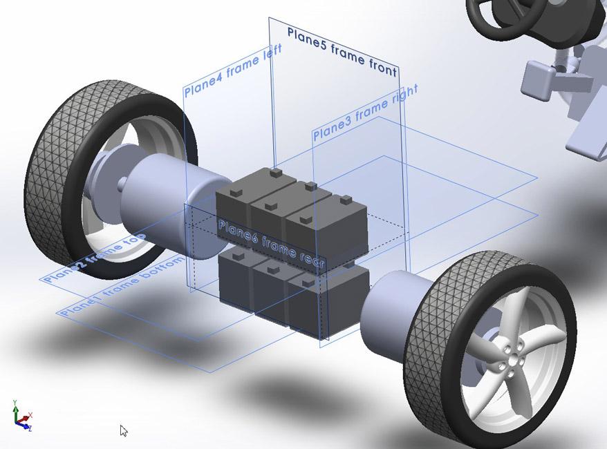
Figure 2a
Lots of planes (reference geometry) define the limits of
the battery box and were set up in the context of the gocart
assembly.
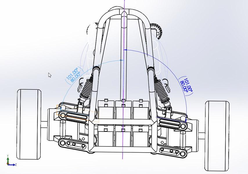
The suspension geometry (relative length of the upper and lower arms) has a major effect on how the wheels engage with the ground. Context-based modeling in 3-D allows for virtual prototyping of various setups for this product.
With the suspension system modeled in the context of the original assembly, we can adjust and experiment with the range of motion. As hinted at in Figure 4b, the motors will swing about 21 degrees relative to the midplane of the cart.
That’s enough with the virtual. Let’s build one and see if it works!
Some of the elements found in the illustrations were sourced from www.3dcontentcentral.com and www.grabcad.com.
Gerald would love to have you send him your comments and questions. You are not alone, and the problems you face often are shared by others. Share the grief, and perhaps we will all share in the joy of finding answers. Please send your questions and comments to dand@thefabricator.com.


The Fabricator is North America's leading magazine for the metal forming and fabricating industry. The magazine delivers the news, technical articles, and case histories that enable fabricators to do their jobs more efficiently. The Fabricator has served the industry since 1970.
start your free subscription
Easily access valuable industry resources now with full access to the digital edition of The Fabricator.

Easily access valuable industry resources now with full access to the digital edition of The Welder.

Easily access valuable industry resources now with full access to the digital edition of The Tube and Pipe Journal.

Easily access valuable industry resources now with full access to the digital edition of The Fabricator en Español.
In this episode of The Fabricator Podcast, Caleb Chamberlain, co-founder and CEO of OSH Cut, discusses his company’s...


