


Contributing Writer
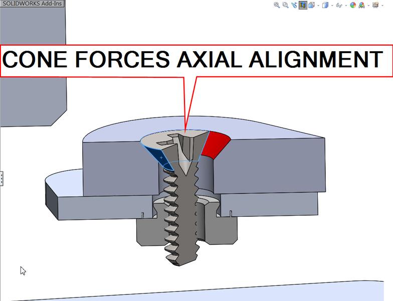
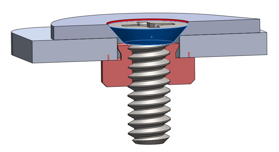
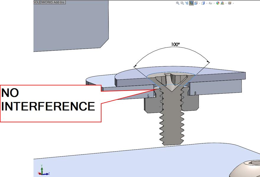
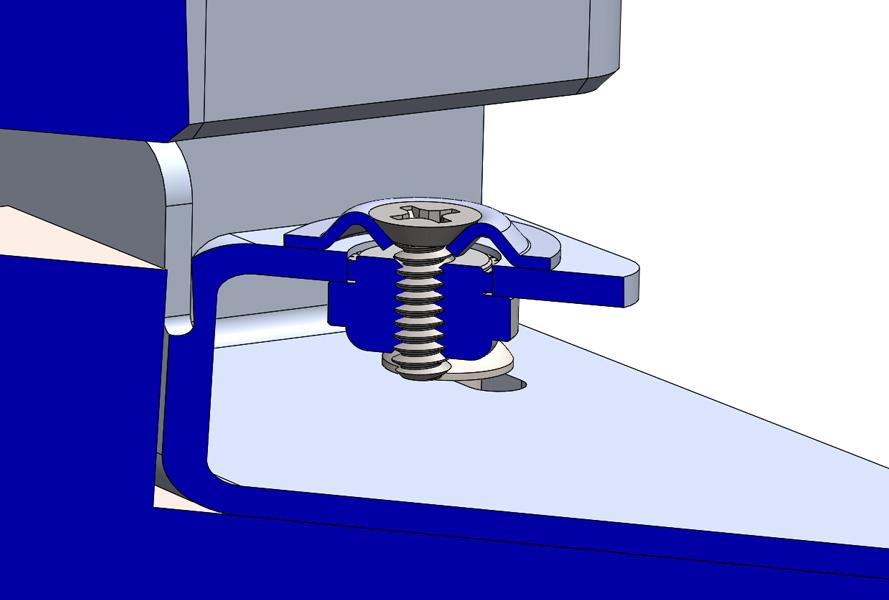
Figure 1
The flat-head screw’s conic head self-centers with the
pocket in the part being clamped. My wife sometimes
thinks of me as a self-centered flat head too.
A countersink is recommended as preparation of the hole for a flat-head screw. CAD jockeys frequently encounter designs that incorporate such features. From the design point of view, an assembly with flat-head screws is relatively easy to model and visualize in 3-D CAD. (Unfortunately, easy to model is not the same as well-designed.)
Countersinks and flat-head screws have their peculiarities; a variety of CAD techniques come into play. It can speed a project’s development to have a library of reusable CAD models at hand. Some built-in CAD tools bring best practices in design for manufacturing to the fore, as well.
Flat-head screws have the obvious benefit of installing flush—more or less—with the surface of the assembly. Perhaps another benefit is that the taper of the screw head self-centers within the countersink pocket. A cross-section view of an assembly featuring a flat-head screw, a countersunk plate, and some sheet metal with a swage nut is shown in Figure 1.
The flat-head screw protrudes into the assembly because of the height of its cone. When thin material is clamped—sheet metal, for example—the protrusion below the surface is one of several important design considerations. For maximum clamping strength when using flat-head screws, keep the thickness of the plate at least equal to the head height. Figure 1 is an example of preventing the cone of the screw from contacting the nut.
Figure 2a shows an example of the impossible. The screw is shown buried into the nut, certainly damaging the threads. This was easy to model, but is not a good design. Figure 2b shows the more likely result: The screw head will fail to tightly clamp the assembly. Note that this model took a little more thought than Figure 2a. Be aware! This sort of modeling error is an easy sin to commit.
When thinner material must be clamped, flat-head screws are available with undercut heads (see Figure 3a). The undercut simply removes part of the cone that would otherwise protrude into the assembly. Removing material from the screw head also removes some of its strength.
As an alternative to undercutting, increasing the angle of the countersink reduces the depth of protrusion (see Figure 3b). While this design may satisfy some size goals, the strength of the 100-degree screw head is decreased because it is thinner.
Note that the wide-angle pocket in Figure 3b boosts the sheet metal’s pull-out strength compared to Figure 3a. (CAD tip: Wider-angle countersinks favor the strength of the clampee; narrower head angles favor the clamper.)
Flat-head screw angles and sizes are standardized. Basically three angles are in common use: 82, 90, and 100 degrees. Note that 90 degrees is almost exclusively found on metric screws. Some rivets sport a 120-degree head. The CAD software will make it easy to comply with industry-standard fasteners by allowing you to select from lists of standard sizes.
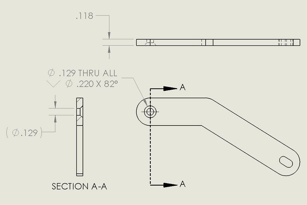
Figure 4a is an example of labor saving in the production of 2-D drawings. The hole specification for the countersink is imported from the 3-D model. No typing was performed during the creation of this drawing. All of the dimensions were added with mouse clicks.
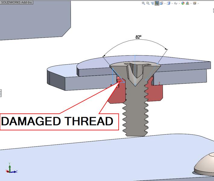
Figure 2a
This image shows an impossible merging of the screw
with the nut. In the real world, threads would be destroyed
by this installation.
In Figure 4a, the 0.129-in.-diameter hole passes all of the way through the 0.118-in.-thick material (see Section A-A). What happens when the material is edited to be something thinner?
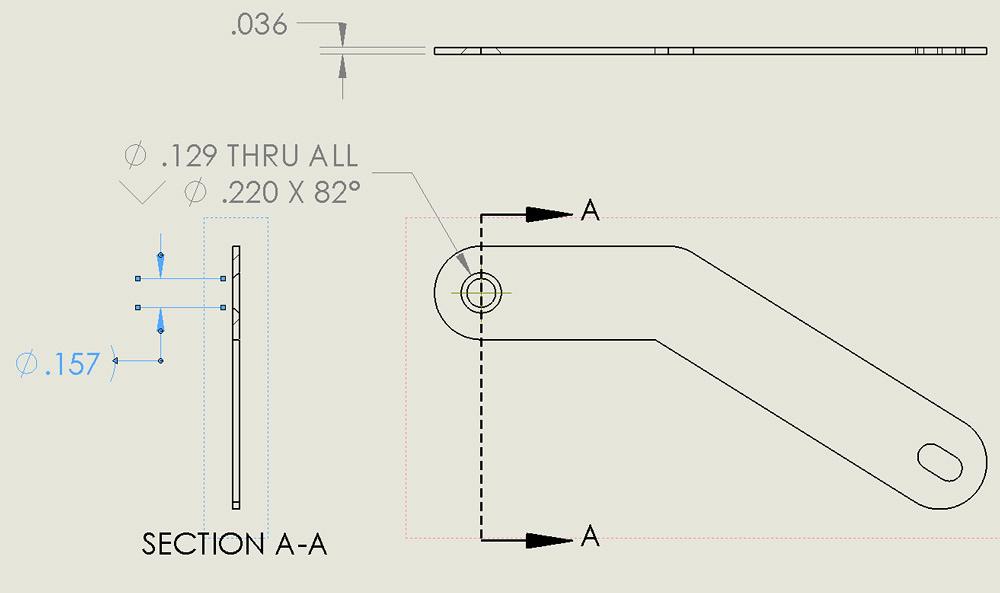
Figure 4b shows a drawing of the same model with reduced material thickness (0.118 in. is now 0.036 in.). Note that the auto-generated hole specification still shows 0.129 in. diameter through all, even though the actual through-hole will be closer to 0.157 in. diameter.
(Design tip: Leave some straight shank for the through-hole. Don’t allow the taper to cut into the through-hole diameter. This habit helps to keep the imported annotations honest, and perhaps more importantly, it keeps a sharp edge feature out of the manufactured item.)
As cited in Figure 1, we place great emphasis on the self-centering characteristic of the flat-head screw. Manufactured screw heads are bound to have some variations. When the cone is not perfectly aligned with the threaded shank, the tightening of the screw introduces an eccentric motion to the sheet metal.
Hole-to-hole variation also exists in our manufactured design. In a situation where the threaded holes are stationary (machined and tapped, for example), the flat-head screws follow the machined pattern. In a good design, the corresponding pattern of countersunk pockets in the cover plate matches the resulting location of the screws.
What can happen with some of these variations? Misalignment between the threaded hole and the countersink pocket creates lateral pressure under the flat-head screw. As a result, the sheet metal tends to warp and the screw head tends to snap off because of the off-center point load.
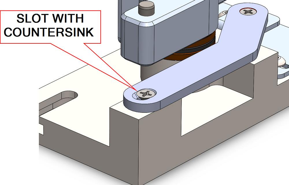
Let’s consider the concept of forgiveness of misalignment from flat-head screws. A slot can be chamfered as a countersink feature (see Figure 5). Such a slot might allow the screw to seat with less side-load stress. However, the absence of material reduces the connection strength.
Another design solution is to constrain the manufacturing tolerances so that the misalignment of the flat-head screws does not cause significant warping of the assembly. Tighter tolerances and thicker materials usually translate into greater expense.
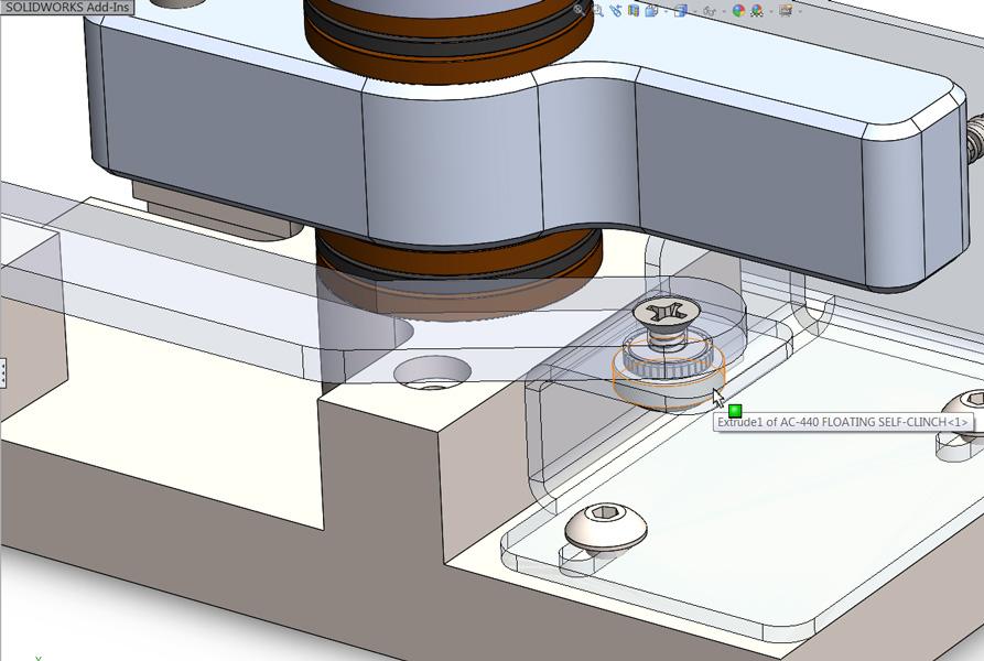
Perhaps a better solution is to allow the threaded hole to change its location as the screw is tightened. As shown in Figure 6, an assembler needs to have access for a wrench to hold the nut. If that is the case, discrete fasteners are the ultimate in forgiveness.
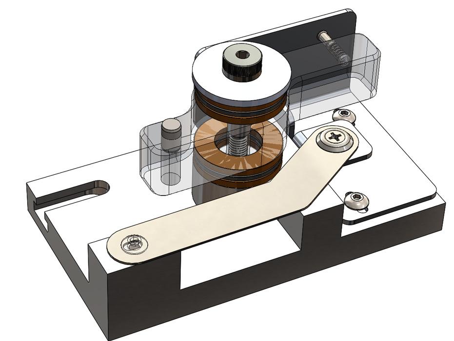
If wrenching is not an option, a cage can be used to keep the nut from spinning and yet hold it in place to prevent accidental loss. Self-clinching floating nuts work very well with flat-head screws; a model of one can be seen hiding behind the transparent aluminum in Figure 7.
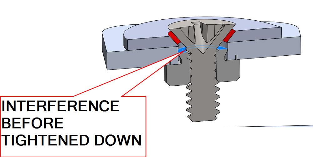
Figure 2b
This image shows the screw’s installation before damage
is done. Note that the screw head is too tall and fails
to clamp tightly.
Some situations occur in which the misalignment of a flat-head screw in its target pocket cannot be overcome by changing the nut or the pocket. One must change the flat-head.
Instead of a countersink, the counterbore is a fine solution for dealing with misalignment between pocket and thread. As an aesthetic detail, the counterbore is distinctive, to put it objectively.
Perhaps the flat-head has some sealing or aesthetic detail that is desired. The use of ferrules (countersink washers) can result in a nice appearance with both strong and stress-free assembly.
Distinctive in its own way, the look of the ferrule might be desirable, but the loose-piece-to-assemble is not. Perhaps the ideal material for the cover is thinner than any flat-head screw can clamp securely.
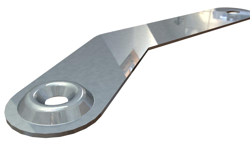
Not to worry! In Figure 8a we see a sheet metal part that has a ferrule embossed into it. This embossed raised countersink works well for sealing, self-centering, and providing some forgiveness in alignment because of the (slight) flexibility of the sheet metal cone.
Figure 8b is a cross-section view showing an installation of a flat-head screw in an embossed ferrule. As a modeling technique, a forming tool model was used in the sheet metal model to create this emboss, which is analogous to physical manufacturing.
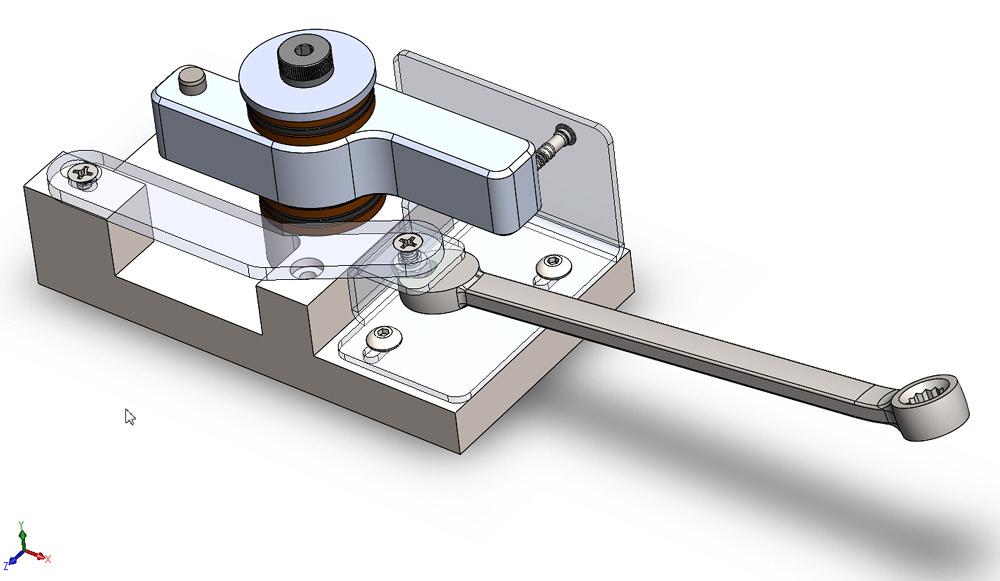
Figure 9 is the final exam. The question is, “What is it?” If you answered “a locking bar that uses a flat-head screw in an embossed ferrule as a precise pivot and a button-head cap screw in a slot as the position adjustment lock,” then that’s totally like pressed cones.
Gerald would love to have you send him your comments and questions. You are not alone, and the problems you face often are shared by others. Share the grief, and perhaps we will all share in the joy of finding answers. Please send your questions and comments to dand@thefabricator.com.


The Fabricator is North America's leading magazine for the metal forming and fabricating industry. The magazine delivers the news, technical articles, and case histories that enable fabricators to do their jobs more efficiently. The Fabricator has served the industry since 1970.
start your free subscription
Easily access valuable industry resources now with full access to the digital edition of The Fabricator.

Easily access valuable industry resources now with full access to the digital edition of The Welder.

Easily access valuable industry resources now with full access to the digital edition of The Tube and Pipe Journal.

Easily access valuable industry resources now with full access to the digital edition of The Fabricator en Español.
In this episode of The Fabricator Podcast, Caleb Chamberlain, co-founder and CEO of OSH Cut, discusses his company’s...


