


Contributing Writer
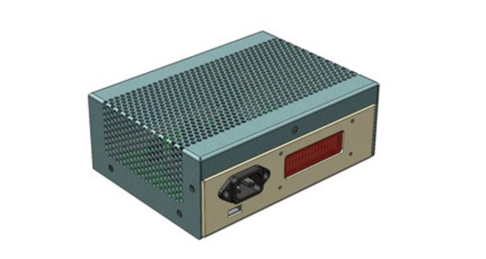
Figure 1a
The perf pattern in this cover warped and oil-canned later in production. Dedicated tooling is not practical while the perforated pattern’s details are changing.
The perforated cover shown in Figure 1a was the conclusion to the previous (January) edition of this column. While the design seemed admirable at the time—at least the design looked functional in 3-D CAD—a hypothetical reality check returned with warped and stressed sheet metal, along with many costly machine cycles to create the perforated zone.
Perhaps, with optimized tooling, processing, and better material selection, this design could be suitable for regular batch production in quantities of hundreds at a time. This scenario excludes dedicated cluster tooling.
Manufacturers of ready-to-use perforated sheet stock do exist. Their cost per hole is excellent. The hypothetical design review committee has suggested that the design adopt that material for the cover.
As an example of life in the 3-D CAD modeling world, the design goals for this project now include:
Here is the outline for what will be done in 3-D CAD:
The use—or possible abuse—of configurations in this project is for the convenience of file sharing with The FABRICATOR’s readership. We offer a pack-and-go .zip file (which can be found at www.thefab ricator.com/page/shop-technology-and-3-d-cad-downloads) that captures legacy information that might be useful to those striving to master the 3-D CAD detail.
Configurations are ideal for modeling screws, nuts, and other types of hardware that simply vary in size. If this were an actual project, a CAD jockey would create a new set of part numbers and files as this cover changes from a single piece of sheet metal into a welded assembly. If instead of configurations you’re interested in discussing workflows for branching projects as revisions occur, please drop us a line.
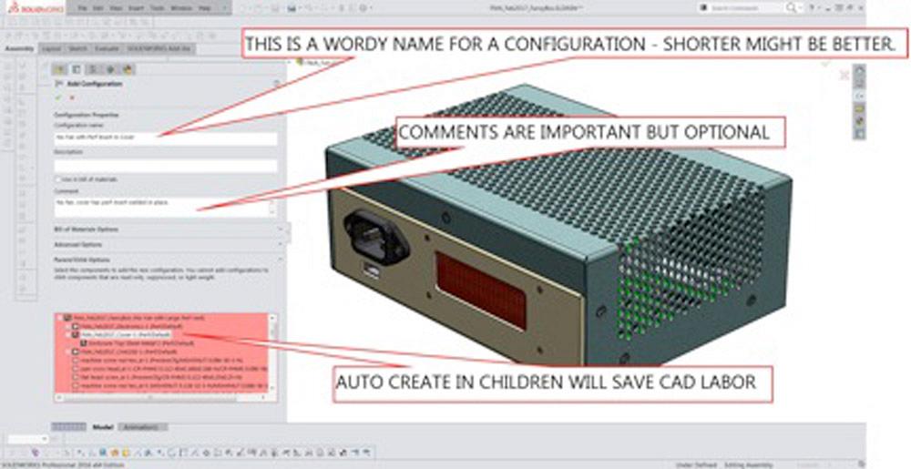
In this example, the top-level assembly has two existing configurations, shown in Figures 1a and 1b. Figure 1a more closely resembles the new design goals because it does not have the fan. With that configuration active, a new configuration is added (see Figure 2).
Here’s a CAD tip in Figure 2: Set the parent/child options to automatically create matching configurations in the children of the part assembly.
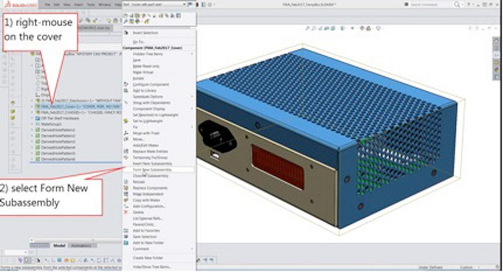
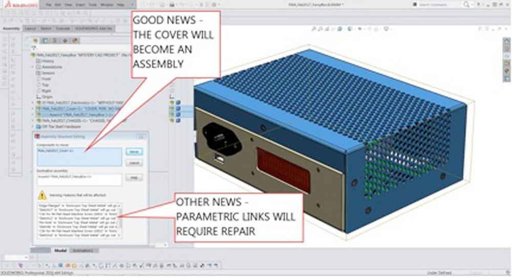
Now that the parent assembly is configured, it is time to configure the children. In this example, the cover changes from being a part to being an assembly. The two-step process is detailed in Figure 3a. First, select the component to make into an assembly, and then select Form New Subassembly from the context menu.
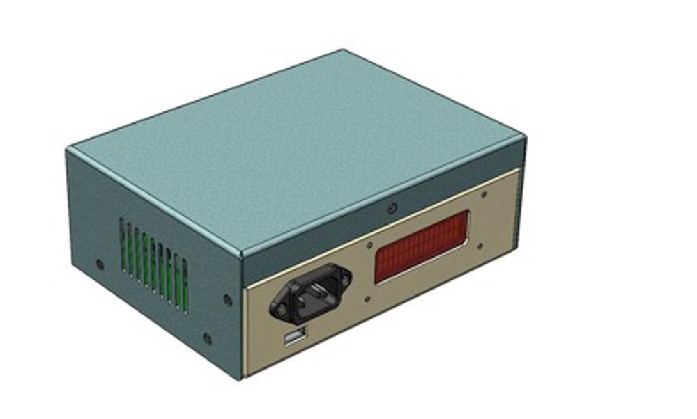
Figure 1b
The legacy design of this cover—simple slots—is to be preserved in the 3-D CAD model. Configurations are used to accomplish this.
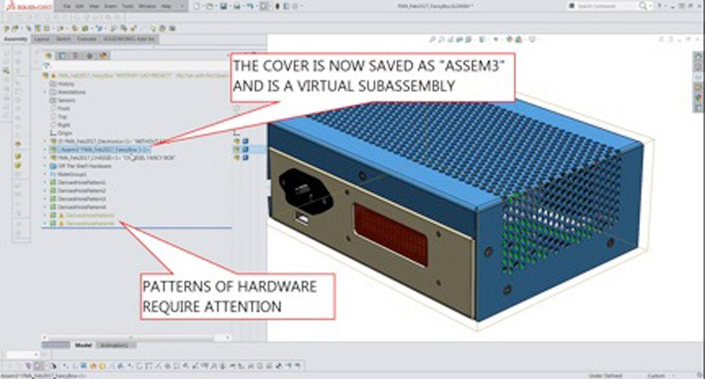
In response, the CAD system updates the hierarchy of the assembly. This damages some of the parametric links in the model. The warning is shown in Figure 3b. The consequence of proceeding is shown in Figure 3c. Patterns for screw holes in the cover have broken links, and their sketches need to be repaired at our convenience.
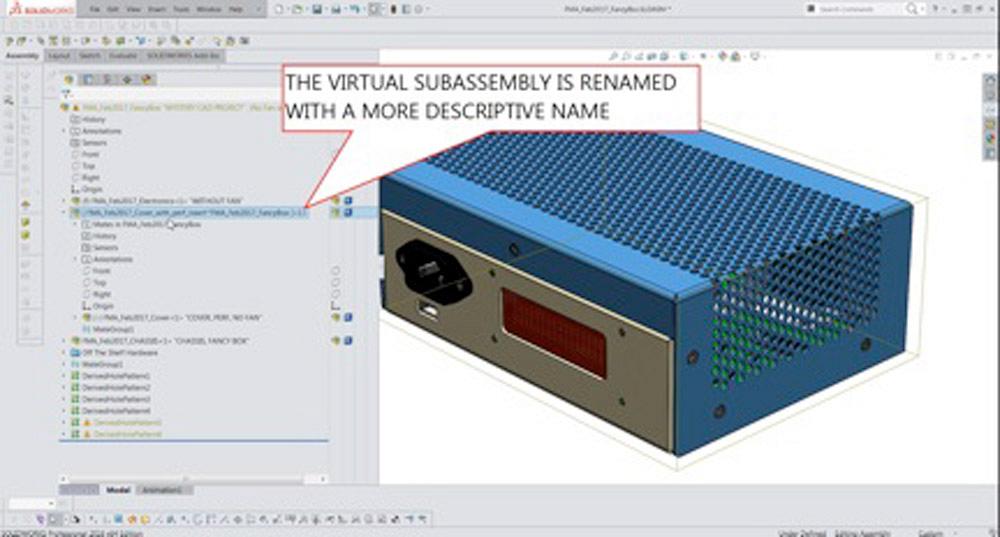
The new virtual assembly was created with the name “ASSEM3.” In Figure 3d that name has been changed, so the cover’s file has a more meaningful name. The new cover assembly has only one of two parts in it so far. The cover frame exists, but the perforated insert does not. Also, the cover frame is still perforated and that needs to change to a cutout.
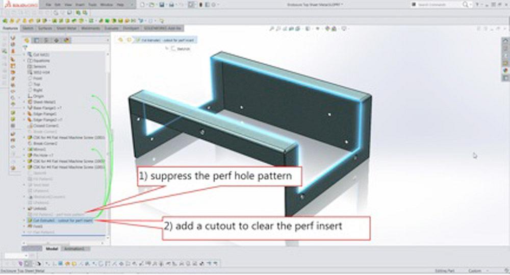
In Figure 4a the perforated cutout pattern has been suppressed. The sketch for the perf boundary was used to create a cutout instead. Note that this sheet metal frame has three configurations now: one for the original design with a fan, one for the second design with a perforated vent pattern, and this third design with a cutout for a perforated insert.
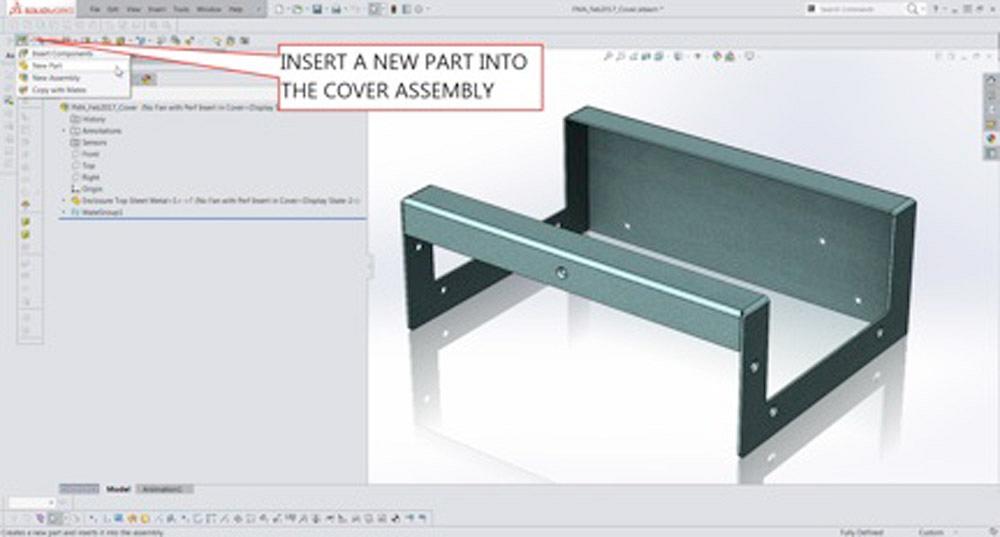
With the cover frame updated, the cover assembly gets a new part inserted into it. Figure 4b details the start of the process: Insert a new part, select a template, save the virtual part, give it a good file name, add features, etc. The new perforated insert part is shown in Figure 5.
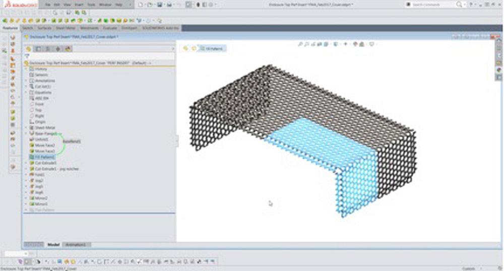
Here’s a CAD tip: Use the Fill Pattern Tool to automatically model the perforated holes. This gives realistic results, but the rebuild time to generate all of the holes is significant.
Here’s another CAD tip: Use the mirror tool to reduce CAD labor. In this example, one-quarter of the part is modeled, and then that is mirrored twice. Design tip: Jog bends around the perimeter serve to stiffen and flatten the part as well as to define the flanges for spot welding.
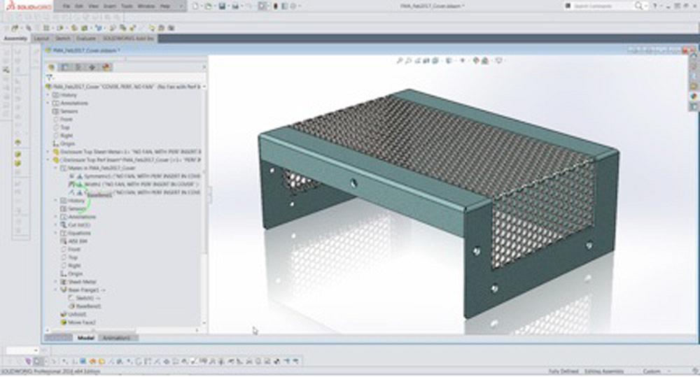
The new perforated insert is installed inside the sheet metal frame for the cover (see Figure 6). In this example, the insert is 22 gauge, and the cover frame is 18 gauge. The jog bends are adjusted to keep the outer surfaces flush.
The new assembly takes a bow in Figure 7. Compared to Figure 1, not much has changed. And yet three design goals have been satisfied:
Gerald would love to have you send him your comments and questions. You are not alone, and the problems you face often are shared by others. Share the grief, and perhaps we will all share in the joy of finding answers. Please send your questions and comments to dand@thefabricator.com.


The Fabricator is North America's leading magazine for the metal forming and fabricating industry. The magazine delivers the news, technical articles, and case histories that enable fabricators to do their jobs more efficiently. The Fabricator has served the industry since 1970.
start your free subscription
Easily access valuable industry resources now with full access to the digital edition of The Fabricator.

Easily access valuable industry resources now with full access to the digital edition of The Welder.

Easily access valuable industry resources now with full access to the digital edition of The Tube and Pipe Journal.

Easily access valuable industry resources now with full access to the digital edition of The Fabricator en Español.
In this episode of The Fabricator Podcast, Caleb Chamberlain, co-founder and CEO of OSH Cut, discusses his company’s...


