


Contributing Writer
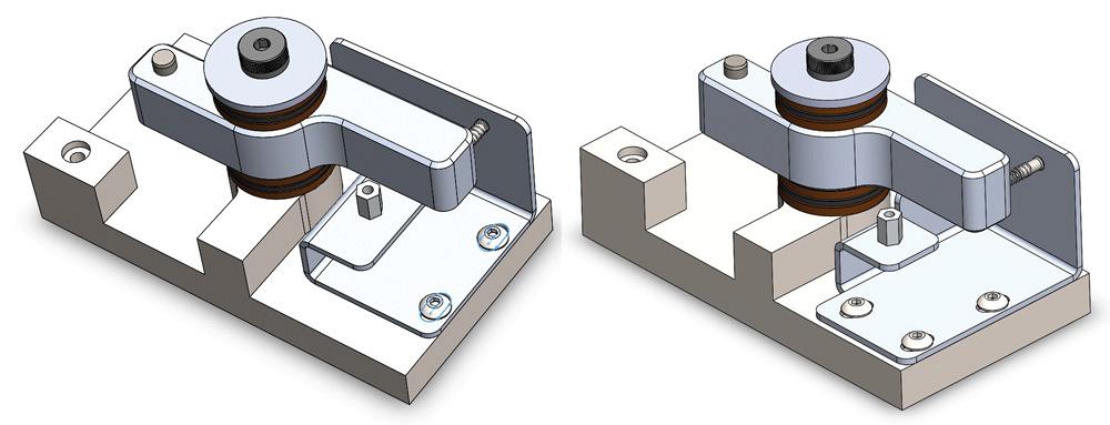
Figure 1a
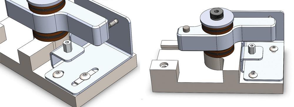
First appearing in March 2015, this model shows a bent
tab to support a spring. The sheet metal bracket is adjusted
with screws in slots. (The screws are not shown.)
As an improvement, the bent tab is replaced, as shown
in Figure 1b.
Regular readers of this column may recall the evolution of the design shown in Figures 1a and 1b. Mike Matusky, Everett, Wash., sure did.
While reading the March column, he saw something askew with the proposed sliding adjustment.
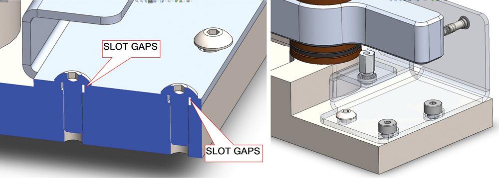
“The two parallel slots in either bracket design don’t keep the bracket from turning … [thus] moving the bent tab or swaged pin out of alignment with the spring seat in the moving arm of the assembly,” he wrote in an e-mail.
Figure 1c confirms Matusky’s prediction. It is indeed possible to keep the screws within the parallel slots but still have the pin completely out of alignment with the spring. (CAD tip: Mates in the assembly can force parts to appear to move perfectly. Don’t be fooled. Actual parts have friction and degrees of freedom that can be difficult to model in CAD.)
With the assumption that we have full authority to alter the design, Matusky continued: “… difficulty in adjusting in service could be prevented by adding a hole to the base and using two slots in line with each other.”
That’s a great suggestion! Figure 2a shows a minimalist approach to improving the adjustment slots. The slots have been relocated to be in line with each other. Tooling access in this design is improved. A slight cost improvement over the bracket shown in Figure 1c is achieved by eliminating a cutout needed for screw driver tooling access.
Depending on the quality of the stamping of the sheet metal, some crowning may be present in the flange with the slots in Figure 2a. This could lead to some unwanted drift during final clamping.
Figure 2b shows another possible implementation of Matusky’s in-line slot idea. The addition of the third screw and slot adds some expense to the design, but allows the person making the adjustment to set sliding tension with two of the screws and clamping force with the third. This tripod clamping method is inherently more stable than the one shown in Figure 2a. This probably will improve upon the unwanted drift of spring pressure as all three screws are tightened for final clamping.
Suppose that the sliding precision of the adjustment is still in need of improvement. Figure 3a is a cross-section view showing clamping screws holding the sheet metal bracket in place. The slots are, by necessity, wider than the screws to allow for manufacturing tolerances. Additionally, the threaded shank of the screw is an inconsistent bearing face against the punched walls of the slots in the sheet metal.
In Figure 3b we’re doing the “Shoulder Bolt Slide.” Sounds good, anyway.
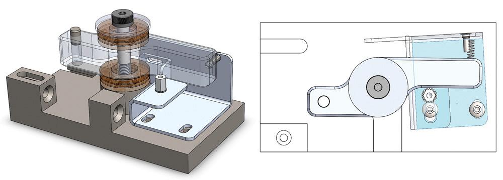
Figure 1b and 1c
(left)This is the May column version. The captive pin is nice.
Problems with screw driver access are addressed in Figure
1c.
(right)This overhead view shows reader Mike Matusky’s prediction
that the bracket can twist out of position. Parallel
slots are not providing any guidance during adjustment
Two of the common screws have been replaced with shoulder bolts. The sheet metal has gained thickness to increase the surface area of the sliding engagement. In this example, the shoulders are 2 mm (0.079 in.) and the sheet metal is 14 gauge (0.075 in.), which makes a fairly nice slide without much rattle.
The side-to-side gap tolerance between the shoulder bolt and the slot can be much tighter because of the precision of the shoulder bolt shanks. These shoulder bolts are only going to serve as guides for sliding. The third clamping screw is an important feature of this design idea.
We could even specify the surface finish of the slots in Figure 3b, but it is getting to be a rather labor-intensive product to manufacture.
Figure 4a takes advantage of our “full control” over the design. Here, we replace the shoulder bolts with a raised island that guides the slot. This works with common screws and probably would work well with a second island in the other slot for additional precision. Note that “in line” is no longer required, as far as the location of the screws goes. That could be important when considering tool access during service.
If we’re willing to change how the part is machined, Figure 4b shows the use of a flat face on the sheet metal to slide against a machined wall feature in the frame. The screws serve only for clamping and have no role in guiding the adjustment.
This exploration of slot designs has resulted in alternatives that have competing merits in terms of cost of fabrication, clamping grip, ease of assembly, and ease of service. As a demonstration of using CAD to visualize design ideas, all of these solutions are presented for consideration before converting raw material.
In the real world, the designs compete in a more sequential manner. One idea follows the next. This chain of revision is necessary because the previous designs had a flaw. Rolling the new revision into production has consequences. What to do with existing inventory? Are field upgrades required?
Another reader who contacted The FABRICATOR after the March column operates in a world where several production lines are fed with common parts. Revisions to those common parts are incredibly complicated to implement.
To help with this, some brands of CAD work with document management systems. But workgroup document management is a topic for another time.
Gerald would love to have you send him your comments and questions. You are not alone, and the problems you face often are shared by others. Share the grief, and perhaps we will all share in the joy of finding answers. Please send your questions and comments to dand@thefabricator.com.


The Fabricator is North America's leading magazine for the metal forming and fabricating industry. The magazine delivers the news, technical articles, and case histories that enable fabricators to do their jobs more efficiently. The Fabricator has served the industry since 1970.
start your free subscription
Easily access valuable industry resources now with full access to the digital edition of The Fabricator.

Easily access valuable industry resources now with full access to the digital edition of The Welder.

Easily access valuable industry resources now with full access to the digital edition of The Tube and Pipe Journal.

Easily access valuable industry resources now with full access to the digital edition of The Fabricator en Español.
In this episode of The Fabricator Podcast, Caleb Chamberlain, co-founder and CEO of OSH Cut, discusses his company’s...


